Iveco Daily. Manual - part 389


  Index      Iveco     Iveco Daily - service repair manual 2004 year


Search            


Content   ..  387  388  389  390   ..


Iveco Daily. Manual - part 389


120

ELECTRIC/ELECTRONIC SYSTEM

D

AILY

Base - May 2004

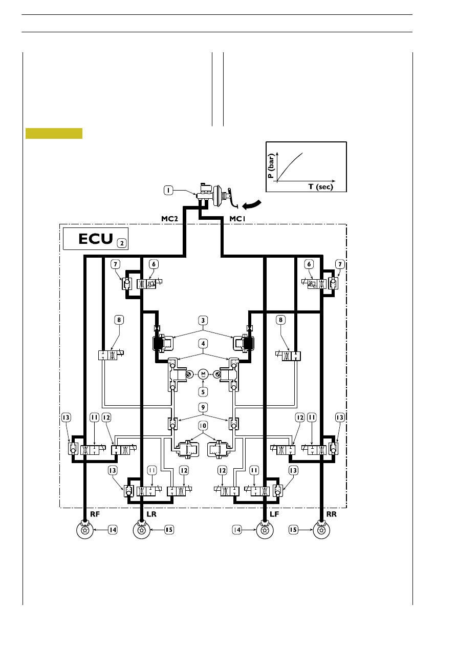
figure  schematically  shows  the  connection  of  the

modulator and its internal components.

Pressure increase
Operating the brake pedal, the pressurised oil can reach the

brake calipers as both the drive solenoid valves "6" and the

supply solenoid valve "11" are open.

1. Vacuum servobrake - 2. Electronic control unit - 3. High pressure accumulator - 4. Recovery pumps - 5. Recovery

pump drive motor - 6. ABD control solenoid valves (setting 90 bar) - 7. One-way safety valves - 8. ABD intake solenoid

valves - 9. ABD one-way valves - 10. Low pressure accumulator - 11. Supply solenoid valves - 12. Discharge solenoid

valves - 13. One-way quick pressure reduction valves - 14. Font axle disk brakes - 15. Rear axle disk brakes

Figure 119

ELECTRIC/ELECTRONIC SYSTEM

121

D

AILY

Pressure lowering
If the sensors detect the tendency of a wheel or wheels to

lock, they inform the control unit which reduces the braking

force  activating  the  supply  solenoid  valves  "11"  and  the

discharge solenoid valves "12".

At the same time, supplying the motor "5" that drives the

pumps "4" it will be possible to recover the excess oil volume

in the high pressure accumulators "3".

SYSTEM OPERATING LAYOUT SHOWING THE PRESSURE MAINTENANCE PHASE

Figure 120

122

ELECTRIC/ELECTRONIC SYSTEM

D

AILY

Base - May 2004

control unit can keep it constant, no longer energising the

discharge  solenoid  valves  "12",  the  motor  "5"  and  the

associated  recovery  pumps  "4",  while  the  supply  solenoid

valves "11" continue being supplied.

SYSTEM OPERATING LAYOUT SHOWING THE PRESSURE MAINTENANCE PHASE

Figure 121

ELECTRIC/ELECTRONIC SYSTEM

123

D

AILY

Cutting in of EBD device
If the sensors detect that one or both wheels tend to lock

in relation to the front wheels, they inform the control unit

which suitably supplies the supply solenoid valves "11" of the

rear axle to optimise the braking force.
A  fault  on  certain  system  components  causes  the  ABS

system to be cut off (displayed by turning on the special

warning light), still leaving the EBD system operational.

If  both  failure  warning  lights  turn on (ABS and EBD) this

means an EBD system failure.
Under  these  conditions  the  braking  force  will  not  be

distributed between the axles, therefore rear wheel locking

may occur with the possibility of skidding.

FP. Rear axle braking force - FA. Front axle braking force - A. Servobrake distribution curve - B. Ideal distribution - 

C. Curve - distribution curve of any porportioning valve - D. EBD system distribution curve

Figure 122


Content   ..  387  388  389  390   ..