Iveco Daily. Manual - part 364


  Index      Iveco     Iveco Daily - service repair manual 2004 year


Search            


Content   ..  362  363  364  365   ..


Iveco Daily. Manual - part 364


WIRING DIAGRAM

PERSPECTIVE VIEW

08000

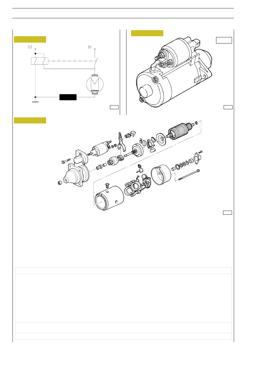
PERSPECTIVE BLOWN-UP VIEW

1. Support - 2. Pinion engagement control electromagnet - 3. Pinion - 4. Pinion engament fork - 5. Rotor - 6. Frame -

7. Inductors - 8. Brush holder support - 9. Cover - 10. Screw

1

2

3

4

5

6

7

8

9

10

Figure 23

Figure 24

Figure 25

74023

8642

5260

24

ELECTRIC/ELECTRONIC SYSTEM

D

AILY

Base - May 2004

Fast diagnosis

Defect

Possible causes

Remedy

Low drawing torque

1. Low battery

Recover

2. Oxidized or loose circuit connecĆ

tions

Check starter motor and battery conĆ

nections

3. Faulty brushes

Check brush slide length and pressure

4. Field coils short circuited

Replace coils

5. Rotor cut out or short circuited

Replace rotor

6. Oval collector

Grind correct or replace

Low drawing torque but engine does

not start

1. Defective free wheel or electromaĆ

gnet

Replace

Pinion disconnected

1. Worn toothed crown

Recover

ELECTRIC/ELECTRONIC SYSTEM

25

D

AILY

Battery

The battery shown below has a 12Vdc 110Ah 460 A power supply voltage and is installed on the left side of the engine

compartment near the EDC control unit (Ref. A of figure).

Requirements
- Case and cover in polypropylethylene plastics PR. 50.100. Matt white case.
- C.S. plugs, blacK. Grids: positive and negative made of Pb Ca.
- Cover integral polypropylene
- Separator: envelope-type polyethylene
- Battery for tropical duty" marked with red color.
- Environmental precautions" plate according to Law no. 126 of 10/04/91 Standards for user information".
- Adhesive label with  Selective disposal" acc. to EEC Directive no. 93/86.

Fast diagnosis

Defect

Possible causes

Remedy

Start defect

1. Low battery

Check battery charge; if regular check

recharge circuit

2. Loose, oxidized or burnt out conĆ

tacts

Recover

3. Starter circuit defective

Cf. start section

Low voltage at component leads

1. Battery at half power

Check battery charge; if regular check

recharge circuit

2. Oxidized  connections

Sand and replace

Electrolyte level often low

1. Over voltage

Check recharge circuit and/or connecĆ

tion tightness

A

Figure 26

73721

WIRING DIAGRAM

7777

8887

8850

8888

Live circuit

Under  current

Function

Terminal

Position

Cable colour

code

0

30

30 -15

30 - 15/A

30 - 15

30 - 50

    -

Services

Users

Services

Starting

30

15

15/A

50

Supply

Services

User cut-off relay during

starting

Starting

I

II

PERSPECTIVE VIEW WITH ASSOCIATED CONNECTIONS AND KEY ROTATION TECHNICAL LAYOUT

SWITCHING SEQUENCE

0. Stop - I. Drive  - II. Starting

30

50

15/A

15

0

I

II

52502

15/A

50

15

30

II

I

0

115º

44º

Figure 27

Figure 28

Figure 29

1171

1125

8654

26

ELECTRIC/ELECTRONIC SYSTEM

D

AILY

Base - May 2004

PERSPECTIVE VIEW OF THE JUNCTION BOX AND ASSOCIATED CONNECTORS AND THEIR SURFACE WITH

CONTACT BLADES

VIEW OF THE ENGINE COMPARTMENT LOCATION

Figure 30

Figure 31

8630

73722

ELECTRIC/ELECTRONIC SYSTEM

27

D

AILY

Interconnection center

This is a shunt center distributing battery positive power via internal jumpers.


Content   ..  362  363  364  365   ..