Iveco Daily. Manual - part 331
 

  Index      Iveco     Iveco Daily - service repair manual 2004 year


Search            


Content   ..  329  330  331  332   ..


Iveco Daily. Manual - part 331


102276

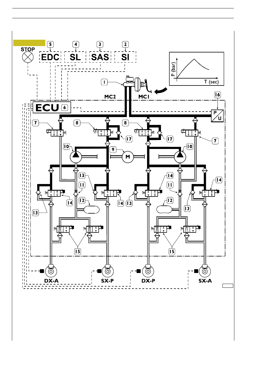
Pressure decrease

1. Vacuum servobrake - 2. Yaw sensor - 3. Steering angle sensor - 4. Longitudinal acceleration sensor -

5. EDC motor control unit - 6. ESP electronic control unit - 7. Intake solenoid valves - 8. Driving solenoid valves -

9. Scavenge pump control motor - 10. Scavenge pumps - 11. Single-acting safety valves - 12. Low pressure

accumulators - 13. Quick pressure decrease single-acting valves - 14. Power supply solenoid valves -

15. Discharge solenoid valves - 16. Pressure sensor - 17. Single-acting valves - DX/A. Front axle right wheel sensor -

SX/A. Front axle left wheel sensor - DX/P. Rear axle right wheel sensor - SX/P. Rear axle left wheel sensor

If the sensors find that the wheel(s) tends to get locked, they will inform the control unit: the latter will reduce the braking power
by actuating power supply solenoid valves “14” and discharge solenoid valves “15”.

At the same time, the excess oil in low pressure accumulators “12” can be recovered by powering motor “9” which drives pumps
“10”.

Figura 46/9

51/13

HYDRO-PNEUMATIC SYSTEM - BRAKES

D

AILY

Revi - February 2005

102277

Pressure maintenance

1. Vacuum servobrake - 2. Yaw sensor - 3. Steering angle sensor - 4. Longitudinal acceleration sensor -

5. EDC motor control unit - 6. ESP electronic control unit - 7. Intake solenoid valves - 8. Driving solenoid valves -

9. Scavenge pump control motor - 10. Scavenge pumps - 11. Single-acting safety valves - 12. Low pressure accumulators -

13. Quick pressure decrease single-acting valves - 14. Power supply solenoid valves - 15. Discharge solenoid valves -

16. Pressure sensor - 17. Single-acting valves - DX/A. Front axle right wheel sensor - SX/A. Front axle left wheel sensor -

DX/P. Rear axle right wheel sensor - SX/P. Rear axle left wheel sensor

When the optimum braking force has been obtained, the control unit will be able to keep such force steady by de-energizing
discharge solenoid valves “15”, motor “9” and its respective scavenge pumps “10”, whereas power supply solenoid valves “14”
will be powered on.

Figura 46/10

HYDRO-PNEUMATIC SYSTEM - BRAKES

51/14

D

AILY

102278

EBD device intervention

1. Vacuum servobrake - 2. Yaw sensor - 3. Steering angle sensor - 4. Longitudinal acceleration sensor -

5. EDC motor control unit - 6. ESP electronic control unit - 7. Intake solenoid valves - 8. Driving solenoid valves -

9. Scavenge pump control motor - 10. Scavenge pumps - 11. Single-acting safety valves - 12. Low pressure accumulators -

13. Quick pressure decrease single-acting valves - 14. Power supply solenoid valves - 15. Discharge solenoid valves -

16. Pressure sensor - 17. Single-acting valves - DX/A. Front axle right wheel sensor - SX/A. Front axle left wheel sensor -

DX/P. Rear axle right wheel sensor - SX/P. Rear axle left wheel sensor

Fp. Rear axle braking force - Fa. Front axle braking force - A. Servobrake distribution curve -

B. Ideal distribution curve - C. Distribution curve of corrector (if any) - D. EBD system distribution curve

If the sensors find that one or both of the rear wheels tend to get locked compared with the front wheels, they will inform the
control unit: the latter will, as a result, power rear axle power supply solenoid valve “14”, so as to optimize the braking force.
Any anomaly of some components of the system will cause the ABS system to be cut off (this condition will be displayed by
the lighting of the respective warning light). Yet, the EBD system operation will be ensured. Simultaneous lighting of both failure
warning lights (ABS and EBD) will indicate a fault in the EBD system; under these conditions, great care shall therefore be taken
while driving, since braking will not be optimized.

Figura 46/11

51/15

HYDRO-PNEUMATIC SYSTEM - BRAKES

D

AILY

Revi - February 2005

102281

ESP device intervention

1. Vacuum servobrake - 2. Yaw sensor - 3. Steering angle sensor - 4. Longitudinal acceleration sensor -

5. EDC motor control unit - 6. ESP electronic control unit - 7. Intake solenoid valves - 8. Driving solenoid valves -

9. Scavenge pump control motor - 10. Scavenge pumps - 11. Single-acting safety valves - 12. Low pressure

accumulators - 13. Quick pressure decrease single-acting valves - 14. Power supply solenoid valves -

15. Discharge solenoid valves - 16. Pressure sensor - 17. Single-acting valves - DX/A. Front axle right wheel sensor -

SX/A. Front axle left wheel sensor - DX/P. Rear axle right wheel sensor - SX/P. Rear axle left wheel sensor

Control unit “6” can brake the single wheels to ensure vehicle stability under dangerous driving conditions.
The signals from yaw sensor “2”, steering angle sensor “3”, and longitudinal acceleration sensor “4”, as well as the speed signals
and the accelerator pedal position, provide information that allows the system to come into operation under vehicle
understeering or oversteering conditions.
Intake solenoid valves “7” and driving solenoid valves “8” will be actuated. At the same time, motor “9” will be actuated, which
controls pumps “10” so that the wheel(s) will be braked in order to correct the path.
Thanks to the CAN line communication with EDC motor control unit “5”, ESP control unit “6” will be able to act on engine
control, too.

Figura 46/12

HYDRO-PNEUMATIC SYSTEM - BRAKES

51/16

D

AILY


Content   ..  329  330  331  332   ..