Iveco Daily. Manual - part 313
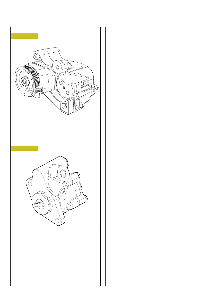
Figure 27
Operation of the power steering pumps for FIA/F1C engines
is similar to that of 8140 engines.
F1C engine power steering pump
Power steering pump overhaul procedure
Replace the power steering pump if poor operation is found.
89008
Figure 28
F1A engine power steering pump
86013
28
STEERING GEAR
D
AILY
Base - May 2004