Iveco Daily. Manual - part 249


  Index      Iveco     Iveco Daily - service repair manual 2004 year


Search            


Content   ..  247  248  249  250   ..


Iveco Daily. Manual - part 249


62884

32445

62885

62887

62888

Figure 16

Figure 17

Figure 18

Figure 19

Figure 20

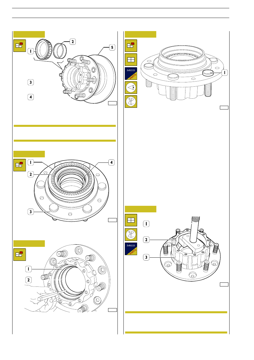
Remove front bearing (1) inner ring and spacer (2).
Remove screws (4) and disconnect the brake disc (5) from the
wheel hub (3).

Remove phonic wheel (1), if any, using suitable equipment.
Remove sealing ring (2) and the rear bearing inner ring (4) set
below from the wheel hub (3).

If it is necessary to replace the pins of the wheel hub (1), before
mounting the new ones, check that the mating surface of the
pin head is free from burrs, dross and blisters.

The pins should be driven in by applying a load on their head
no greater than 2000 kg.

After driving them home, check that the pins are perfectly in
touch with the hub: maximum orthogonal tolerance 0.2 mm.

Use handle 99370007 (1) and beater 99374093 (2) to fit
taper roller bearing outer rings into the wheel hub.

Use a suitable punch to remove the rear taper roller bearing
outer ring (1). Repeat this operation to remove the front
taper roller bearing outer ring.

Refitting

Check the brake disc as described in the ”Brake”
section.

NOTE

This operation shall be performed using a press until
positioning the rings at 5 mm from their abutting
end, their fitting shall be then completed by hand.

NOTE

76

REAR AXLE 450517/2

D

AILY

Base - May 2004

62932

62896

62938

62897

Figure 21

Figure 22

Figure 23

Figure 24

Lubricate the sleeve and the sealing ring supporting ring (1)
with TUTELA W140/M-DA (SAE 85W140) oil.

Use suitable rope and hoist to fit wheel hub (1) on sleeve (4).
Lubricate spacer (2) and outer bearing inner ring (3) with
Tutela W140/M-DA and fit them on sleeve (4).

Lubricate rear taper roller bearing inner ring (4) with SAE W
140 M-DA oil and fit it to wheel hub (5).
Use tool 99374132 (2) provided with proper handle
99370006 (1) to fit sealing ring (3).

Fit the brake disc (3) on the wheel hub (1) and tighten the
fastening screws (2) to the specified torque.

Fit the phonic wheel, if any, on the wheel hub.

Use tool 99374132 (2) side to position the sealing
ring (3) at 1.5 mm from wheel hub side surface.

NOTE

Phonic wheel fitting shall be performed after heating
it at 150ºC.
When fitting is over, check whether the phonic
wheel is resting perfectly on the hub seat.
Check whether phonic wheel squareness and
oscillation is lower than 0.2 mm.

NOTE

Check and, if necessary, adjust the clearance
between the parking brake drum and shoes as
described in the Brakes section.

NOTE

REAR AXLE 450517/2

77

D

AILY

Refitting

62898

62900

62899

62891

62902

62903

Figure 25

Figure 26

Figure 27

Figure 28

Figure 29

Figure 30

Fit the safety washer (3) so that the clip is guided properly into
rear axle casing sleeve groove.
Tighten ring nut (4) with wrench 99357080 (1) and
dynamometric wrench (2), tighten the new ring nut (4) to the
specified torque.

Position the dial gauge 99395684 (1) with a magnetic base
on the wheel hub (3) and rest the rod on the sleeve (2).

Check whether wheel hub end play is falling between 0 and
0.16 mm.

Use tool 99395026 (2) and the dynamometric wrench
99389819 (1) to check whether the wheel hub rolling torque
is falling between 0 and 4 Nm (0 - 0.4 kgm).

After checking the end play and the rolling torque, check
whether one of the adjustment nut (1) holes is coinciding with
one of the safety washer holes otherwise loosen the
adjustment nut (1) until it is possible to fit the fastening screw
(2). Tighten the fastening screw (2) and the adjustment nut to
the specified torque.

Smear the contact surface between axle shaft (3) and wheel
hub (1) with IVECO sealing compound 1905685.
Fit axle shaft (3), tighten the fastening screws (2), excluding
those set between the two wheel hub marks (see Figure 30)
with tool 99370317 (4) lock wheel hub (1) rotation.

Set horizontally to ground the two holes (1) located between
the wheel hub marks and pour through 0.2 l of W140 M-DA
oil on each wheel side.

Smear the threaded section of the screws acting as plug with
IVECO sealant 1905683 and tighten to the specified torque.

78

REAR AXLE 450517/2

D

AILY

Base - May 2004

62904

Figure 31

Position brake calliper (1) including the brake lining on the
supporting flange (2).
Tighten the fastening screws to the specified torque.

62880

Figure 32

Remove the rear axle assembly from the overhaul stand. Refit
brake fluid pipes (2 and 3) to rear axle casing and brake
callipers (1).
Fill rear axle casing with oil in the specified amount and
quality.

Figure 33

Figure 34

Remove the 4 screws (1) including washers and disconnect
the differential locking device (2).
When refitting, replace the gasket located between
differential locking device and rear axle casing.
Tighten screws (1) to the specified torque.

62906

DIFFERENTIAL LOCKING DEVICE SECTION

Differential locking device engagement/disengagement lever
stroke shall be equal to 5 mm.

62907

526210

DIFFERENTIAL REPAIR
OPERATIONS

526260

Differential locking

The brake lining with the wear sensor shall be fitted
on brake calliper piston side.
Comply with BRAKE section requirements to
move back the brake calliper piston.

NOTE

REAR AXLE 450517/2

79

D

AILY


Content   ..  247  248  249  250   ..