Iveco Daily. Manual - part 177
Revi - February 2005
Figure 273
75574
771034
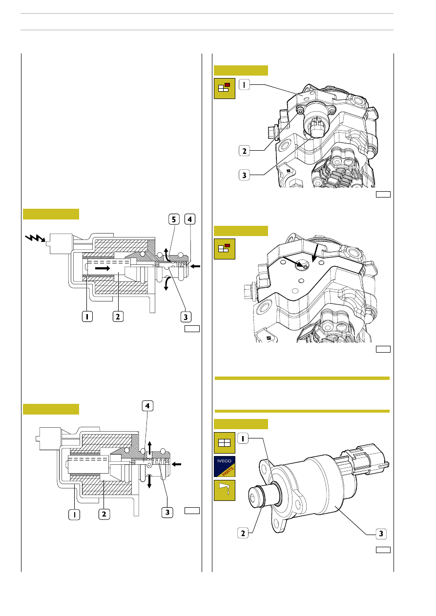
Pressure regulator
75575
Figure 274
Accurately clean high pressure pump.
Take off screws (2) and unthread pressure regulator (3) from
high pressure pump.
88406
Figure 274/1
Replacing pressure regulator
Figure 274/2
88407
Accurately clean the seat (
→) of pressure regulator and the
connection surface (
→) of the regulator.
For cleaning, do not use a tool which could damage
the surfaces and pay attention that impurities are
not introduced into channels.
NOTE
88408
Mount new seal rings (1 and 2) on pressure regulator (3) and
lubricate the rings with vaseline.
Figure 274/3
The fuel pressure regulator is mounted on the low-pressure
circuit of the CP3 pump. The pressure regulator modulates
the amount of fuel sent to the high-pressure circuit according
to the commands received directly from the engine control
unit. The pressure regulator is mainly composed of the
following components:
- connector
- casing
- solenoid
- pre-load spring
- shutter cylinder.
When there is no signal, the pressure regulator is normally
open, therefore with the pump providing maximum delivery.
The engine control unit, via the PWM (Pulse Width
Modulation) signal, modulates the change in fuel flow rate in
the high-pressure circuit by partially closing or opening the
sections of passage of the fuel in the low-pressure circuit.
Operation
1. Solenoid — 2. Magnetic core — 3. Shutter cylinder —
4. Fuel inlet — 5. Fuel outlet.
When the engine control unit governs the pressure regulator
(via PWM signal), the solenoid (1) is energized that, in its turn,
generates the movement of the magnetic core (2). The shift
of the core causes the shutter cylinder (3) to move axially,
choking the flow of fuel.
1. Solenoid — 2. Magnetic core — 3. Pre-load spring —
4. Shutter cylinder.
When the solenoid (1) is not energized, the magnetic core is
pushed into the rest position by the pre-load spring (3). In this
condition, the shutter cylinder (4) is in such a position as to
offer the fuel the greatest section of passage.
604
F1C ENGINE
D
AILY
Base - May 2004