Iveco Daily. Manual - part 159


  Index      Iveco     Iveco Daily - service repair manual 2004 year


Search            


Content   ..  157  158  159  160   ..


Iveco Daily. Manual - part 159


88272

88274

90311

88275

88276

88277

Figure 47

Figure 48

Figure 49

Figure 50

Figure 51

Figure 52

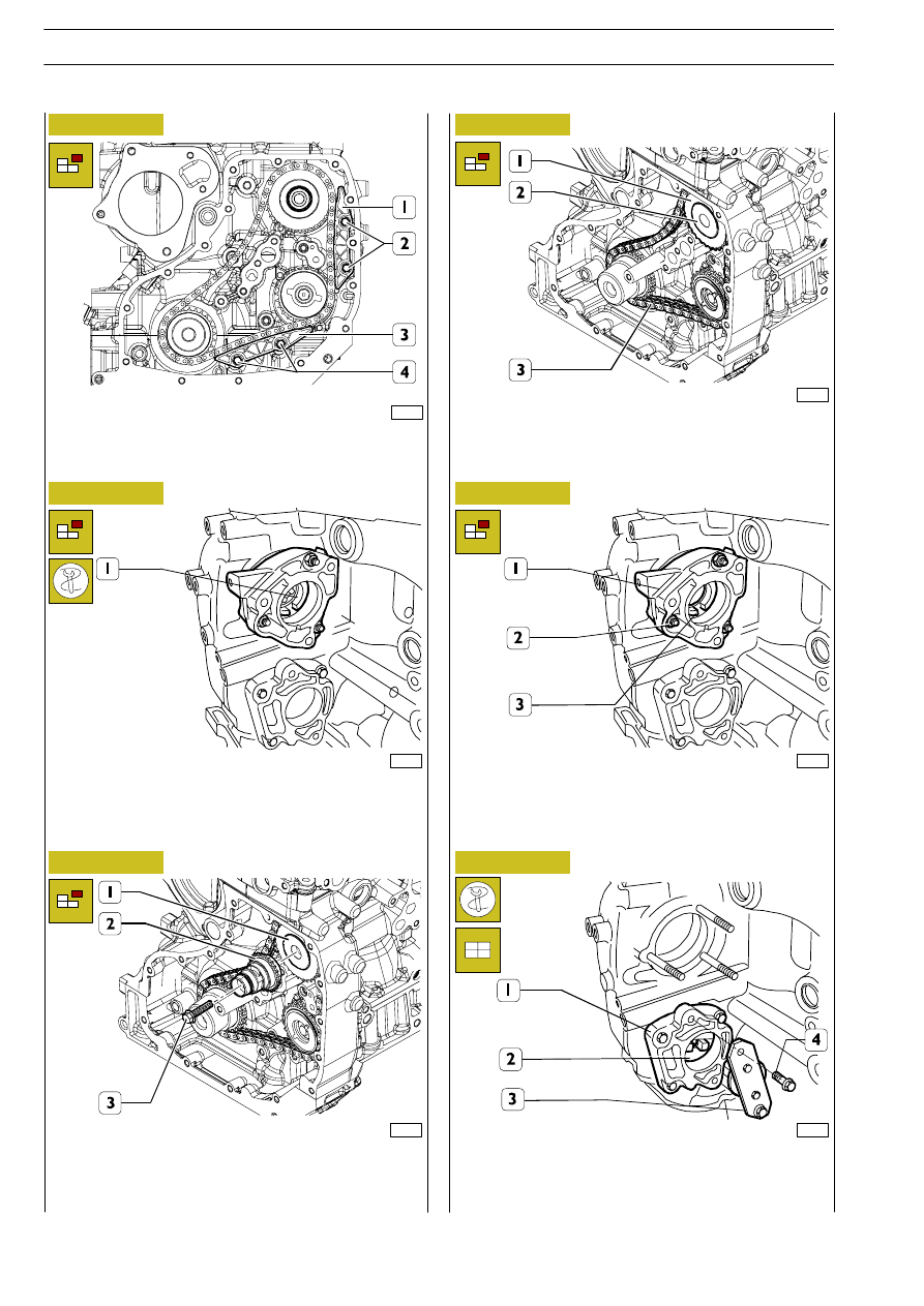
Remove the screws (2) and the side fixed skid (1).
Remove the screws (4) and the lower fixed skid (3).

Stop the rotation of the high pressure pump control shaft (1)
by inserting the suitable wrench inside it.

Remove the screw (3) and the stem with the drive gear (2)
from the high pressure pump control shaft (1).

Remove the gear (1) and the chain (3) from the high pressure
pump control shaft (2).

Remove the high pressure pump control shaft (3).
Remove the nuts (2) and the support (1).

Stop the rotation of the hydraulic power steering pump
control shaft (2) by inserting tool 99360187 (3) in the shaft
and fastening the tool on the support (1) by means of the
screws (4).

532

F1C ENGINE

D

AILY

Base - May 2004

88278

88280

88279

88281

88282

88283

Figure 53

Figure 54

Figure 55

Figure 56

Figure 57

Figure 58

Remove the screw (2) and the gear (1) from the hydraulic
power steering control shaft (3).

Remove the hydraulic power steering control shaft (3).
Remove the nuts (2) and the support (1).

Remove the screws (1) and take off the over-head (2) from
the cylinder head (3).

Remove the hydraulic tappets (1) with the rocker arms.
Remove the gasket (2).

Take out the screws (1) and remove the cylinder head (2).

Remove the cylinder head gasket (1).

Check the protrusion of the pistons (2) as
described under the relevant heading to check the
possibility of facing the crankcase if it has deformed.

NOTE

F1C ENGINE

533

D

AILY

Base - May 2004

88284

88738

88285

88286

88287

Figure 59

Figure 60

Figure 61

Figure 62

Figure 63

Remove the screws (2) and take off the oil sump (1) with its
gasket and frame (3).

Remove the screws (2) and the suction rose (1).

Take out the screws (2) and remove the connecting rod caps
(3).
Extract the pistons (1) from the top of the crankcase.

Block rotation of the flywheel (1) with tool 99360306 (4).
Take out the screws (2) and remove the engine flywheel (1).
Take out the guard (3).

Apply tool 99340060 (2) to the rear O-ring (1) and extract
it from the crankcase.

On the same side of the connecting rod and its
associated cap, indicate the number of the cylinder
from which the connecting rod has been removed.
Keep the bearing shells in their respective housings
since, if they are used, they will need to be fitted in
the position found during removal.

NOTE

534

F1C ENGINE

D

AILY

Base - May 2004

88288

87793

88289

75290

Figure 64

Figure 65

Figure 66

Figure 67

Remove the screws (2) and take off the oil sump (1) with its
gasket and frame (3).

With the aid of a hoist and a rope, remove the crankshaft (1).

Take out the couplings (1) and remove the oil jets (2).

The central half-bearing (3) is fitted with shoulder half-rings.

Note the assembly position of the top main bearing
shells (2) since, if they are reused, they will need to
be fitted in the position found during removal.

NOTE

Note the assembly position of the top main bearing
shells (2) since, if they are reused, they will need to
be fitted in the position found during removal.

NOTE

On completing engine removal, it is necessary to
clean the removed parts thoroughly and check
their integrity.
The following pages give the instructions for the
main checks and measurements to make in order
to determine whether the parts can be reused.

NOTE

F1C ENGINE

535

D

AILY

Base - May 2004


Content   ..  157  158  159  160   ..