Iveco Daily. Manual - part 98


  Index      Iveco     Iveco Daily - service repair manual 2004 year


Search            


Content   ..  96  97  98  99   ..


Iveco Daily. Manual - part 98


75474

75475

75476

Figure 163

Figure 164

Figure 165

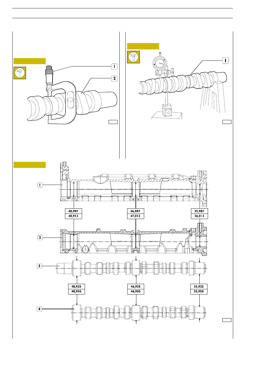
Using a micrometer (1), measure the diameter of the pins (2)
of the camshaft and, using a bore meter, measure the
diameter of the supporting seats in the overhead.
The difference between these two measurements gives the
existing clearance.
The nominal assembly clearance is 0.037

÷ 0.088 mm.

541210

Camshaft

Checks

The surfaces of the shaft supporting pins and of the cams
must be finely honed; if there is any sign of meshing or
scoring, replace the shaft.

541211

Checking cam lift and pin alignment

Set the shaft (1) on tailstocks and, using a dial gauge on the
middle mounting, check that the alignment error is no greater
than 0.04 mm; replace the shaft if it is. In addition, check the
cam lift: it must be as prescribed; replace the shaft if it is any
different.

MAIN DATA, CAMSHAFT PINS AND SEATS

1. Intake valve camshaft seats — 2. Exhaust valve camshaft seats — 3. Intake valve camshaft — 4. Exhaust valve camshaft.

F1A ENGINE

D

AILY

370

Base - May 2004

75471

75478

75477

75479

75469

Figure 166

Figure 167

Figure 168

Figure 169

Figure 170

Lubricate the supporting pins of the shafts (2 and 3) and fit
them in the overhead (1).

Position the overhead (1) and secure it on the mounting
SP.2271 (2).
Position the camshafts (4 and 5) so as to be able to insert the
pins 99360614 (3) into their radial holes through the
threaded holes of the overhead.

Compress the tightener so as to be able to insert a suitable
pin (2) into the hole (

→) of the chain drive (1).

Fit the chain drive (2) on the camshafts and secure it to the
overhead (1) tightening the screws (8) to the prescribed
torque.

Screw down the screws (4) and (7) with the washers (5) and
(6) and tighten them as follows:

- Tighten the screw (7) to a torque of 50 Nm.

- Close further with an angle of 60

°.

- Take out the pin (5).

- Tighten the screw (4) to a torque of 50 Nm.

- Close further with an angle of 60

°.

Fit on the rear cover (2) with a new gasket and tighten the
fixing screws (1) to the prescribed torque.

α

In this operation, take care not to damage the
overhead supporting seats.

NOTE

Use the goniometer 99395216 for the angle
closing.

NOTE

F1A ENGINE

371

D

AILY

Base - May 2004

Assembling overhead

75468

75482

75481

75281

75483

Figure 171

Figure 172

Figure 173

Figure 174

Figure 175

Fit a new seal (3) on the cover (2) and fit this in the overhead.

Fit on the seal (1).

Lubricate the shank of the camshaft.

Using the keying device 99374458 (3), fit the seal (2) in the
overhead (1).

Fit the toothed pulley (1) onto the camshaft so as to align the
hole of the pulley with that of the overhead and insert the
tool 99360608 (4) into these holes. Screw down the screw
(3) together with the washer (2) without tightening fully.

Fit the oil pressure control valve (1) in the crankcase.

Fit on the plug (2) with the seal (3) and tighten it to the
prescribed torque.

Fit the centring tool 99396037 (2) onto the shank of the
crankshaft.

Mount the oil vacuum pump assembly (1) with a new gasket
and tighten the screws (1-15) according to the following
procedures:

- Tighten the screws from no. 1 to no. 6 to a torque of 5

±1 Nm while checking that the tool 99360037 (2) turns
freely.

- Tighten the screws from no. 7 to no. 15 to a torque of

10

±1 Nm.

- Tighten the screws from no. 1 to no. 6 to a torque of 10

±1 Nm.

- After checking that tool 99360037 (2) turns freely,

remove it.

540442

Assembling front seal ring

The toothed pulley (1, Figure 173) is not locked on
the shaft since it must be able to turn when fitting
and tensioning the timing belt. For the same reason,
keep the tools 99360608 (4, Figure 173) and
99360614 (3, Figure 167) fitted.

NOTE

F1A ENGINE

D

AILY

372

Base - May 2004

Lubricate the shank of the crankshaft.

Screw down part (3) of tool 99346254 in the crankshaft and
place the seal (2) on the part (3).

Key part (5) of tool 99346254 onto part (3), screw down the
nut (4) until the seal (2) gets into position in the seat of the
oil vacuum pump assembly (1).

Take out the tool 99346254 (3, 4 and 5).

75484

75485

75280

75279

75486

Figure 176

Figure 177

Figure 178

Figure 179

Figure 180

Turn the crankshaft so as to be able to insert tool 99360615
(5) into the hole in the crank of the crankshaft, through the
hole in the oil vacuum pump assembly (1), to block crankshaft
rotation.

Mount the gear (2), screw down the screw (3) together with
the spacer (4) and tighten it to the prescribed torque.

Mount the speed sensor (1) with a fresh gasket and tighten
the fixing screw (2) to the prescribed torque (if applicable).

Fit on the compressor mounting (3) and tighten the fixing
screws (4) to the prescribed torque.

Mount the air-conditioner compressor (1) (if applicable) and
tighten its fixing (2) screws to the prescribed torque.

Mount the oil pressure transmitter (3) with a fresh gasket.

Mount the heat exchanger (1) with a fresh seal and tighten
the coupling (2) to the prescribed torque.

Do not remove the tool 99360615 (5) as it will be
needed for fitting the timing drive belt.

NOTE

F1A ENGINE

373

D

AILY

Base - May 2004


Content   ..  96  97  98  99   ..