Iveco Daily. Manual - part 78
75817
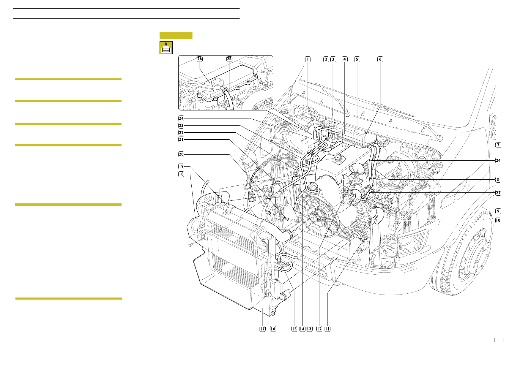
Figure 2
- Take the cap (2) off the expansion tank (4).
- Unscrew the coolant plug (16), under the radiator (17),
and drain the cooling system.
- Disconnect the pipe (25) from the coalescence filter (26)
and from the air intake pipe (14).
- Disconnect the pipes (12) and (13) from the heat
exchanger, intake manifold and turbocharger.
- Unscrew the air filter bracket fasteners (20) to help
extract the air intake pipe (21) from the duct (18) on the
radiator assembly.
- Disconnect the pipe (22) from the duct (19) and (23)
from the engine.
- Disconnect the tube (3) from the expansion tank (4).
- Unscrew the screws (11) to remove the radiator
assembly (17) together with the heat exchanger.
- Disconnect the coolant pipes (8) and (24) from the rigid
three-way pipe (27), freeing them from any clamps (7).
- Disconnect the heater delivery pipe (1).
- Unscrew the fasteners (6) to remove the expansion tank
(4), disconnecting the level sensor’s electrical connection.
- Take the soundproofing cover (5) off the cylinder head
after removing the oil filler cap.
- Disconnect the coolant pipes (9 and 10).
Close the turbocharger air outlet appropriately to
prevent foreign bodies accidentally getting inside
and damaging it.
NOTE
Vehicles with an air-conditioner in the cab should
have the electrical connection (15) disconnected
from the drier filter.
NOTE
In case of vehicles equipped with cabin internal
conditioner, proceed as follows:
- vehicles equipped with drying filter separated
from the condenser:
put the radiator (complete with the condenser
and
drying
filter)
back
in
the
engine
compartment, taking care not to subject the
conditioning system pipes to tension;
- vehicles equipped with drying filter built into the
condenser:
blow gas off the air-conditioning system, as
described in the relevant chapter in the
“Bodywork
and
chassis”
section,
then
disconnect the pipes from the condenser and
seal both the pipes and their respective fittings
on the condenser to prevent moisture and
impurities from penetrating into the system.
NOTE
Revi - February 2005
294
ENGINE F1A
D
AILY
Base - May 2004