Iveco Daily. Manual - part 9


  Index      Iveco     Iveco Daily - service repair manual 2004 year


Search            


Content   ..  7  8  9  10   ..


Iveco Daily. Manual - part 9


543411

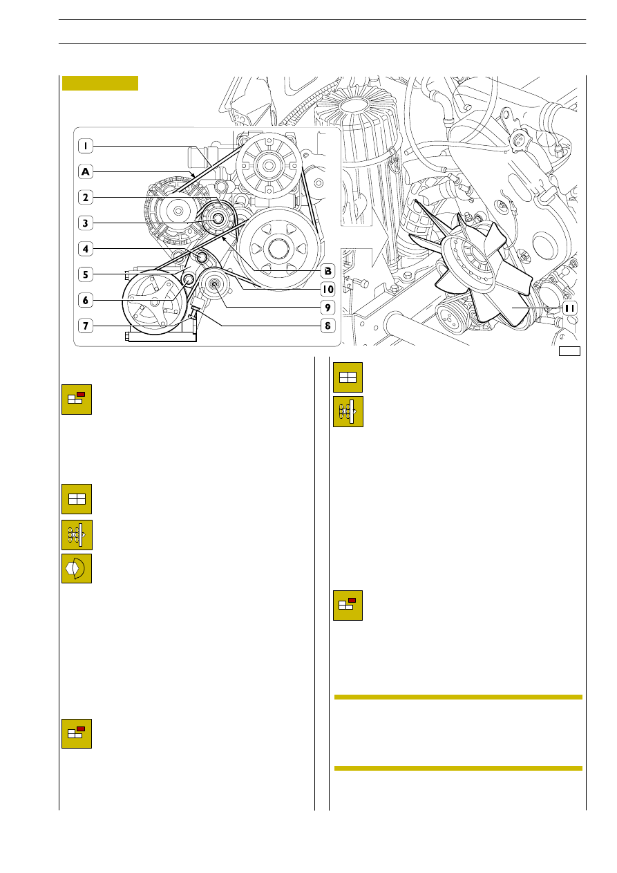
Replacing water pump - alternator
drive belt

If this is not so, turn the screw (7) appropriately. Lock the
screws (4 and 6) at the required tightening torque.
Unscrew the screw (7) by two turns and lock the nut (8) at
the required torque.
Mount the radiator assembly and the remaining parts as
described for refitting the engine assembly.

Disassemble the compressor drive belt, if there is one, as
described under the relevant heading.
Cancel the action of the automatic tightener (2) with the
screw (3) and remove the water pump - alternator drive belt
(1).

Figure 13

543910

Replacing air-conditioning compres-
sor drive belt

Disassembly

Set the vehicle on a lift or over a pit.
From underneath the vehicle, detach the central
soundproofing guard.

Loosen the screws (4 and 6) fixing the tensioner (5) and the
nut (8).
Remove the belt (10) driving the compressor.

50958

Mount the drive belt (10), taking care to position its
ribs properly in the respective races of the pulleys.
Turn the screw (7) to lightly tension the belt (10).
Turn the crankshaft by one turn. Using the ap-
propriate instrument, check that in section B, com-
pressor/crankshaft, the frequency is 160

±10 Hz,

corresponding to a load of 500

± 50 N.

Assembly and adjusting belt tension

Disassembly

Assembly and adjusting belt tension

Mount the drive belt (1) taking care to position its ribs
correctly in the respective races of the pulleys.
Turn the screw (3) to release the automatic tightener (2).
Turn the crankshaft by one turn to settle the belt.
With suitable equipment, measure the tension of the belt (1)
in the section A, crankshaft / water pump / alternator, that
should be 140

± 5 Hz.

Mount the compressor drive belt, if there is one, and adjust
the tension as described under the relevant heading.

543411

Changing the timing system driving
belt

Disassembly

Following the procedures described for removing the engine,
take out the radiator assembly without disconnecting the
air-conditioning system pipes from the condenser and from
the drier filter and put it suitably aside in the engine bay.

For this operation it is not necessary to remove the
bumpers, it is sufficient to remove the air duct from
the radiator and, for vehicles with engine 8140.63,
to remove the screws securing the intake filter air
inlet to the radiator.

NOTE

ENGINES 8140

17

D

AILY

Base - May 2004

Figure 14

Remove the air-conditioner compressor drive belt (7) (if
there is one) and the water pump / alternator drive belt (6)
as described under the relevant headings.
Remove the transverse air duct (3) without disconnecting
the fuel pipe from the solenoid valve and the electric cables.
Put it appropriately to one side in the engine bay (8140.63
engine excluded).
Take out the screw (11) securing the pulley and remove this
from the crankshaft.
Remove the top (2) and side (1) soundproofing covers, if
present.
Remove the top timing cover (4).
Arrange the engine so that cylinder piston 1 is at firing stroke
TDC as follows.
Insert tool 99360608 (19) in hole (

⇒) of transmission cover

(20) from underneath the vehicle.
Turn the crankshaft slowly in the direction of rotation until
the following conditions occur:
1) hole (15) of the crankshaft timing gear is facing
downwards;

2) references and on the tappet cover and on the
camshaft pulley coincide;
3) tool 99360608 (19) is inserted in the engine flywheel
groove (18).

86142

Removal

Remove the nut (16) securing the belt-tightening roller (17).
Remove the bottom timing cover (10). Insert a special
wrench (12) between the pin (14) and the push rod (13) so
as to cancel its pressure on the belt-tightening roller (15).
Remove the timing belt (5).

For engines 8140.43C - 814063 only (engines with
rotary injection pump), in these conditions, stop
the injection pump pulley (9) from turning by
inserting another 99360608 tool through hole (8)
and that of the auxiliary unit.

NOTE

When removing the cogged belt after travelling
≥ 30000 km, replace it no matter what its state of
efficiency.

ENGINES 8140

18

D

AILY

Base - May 2004

Tighten the nuts securing the tightener roller (7) at the
torque of 37

÷ 45 Nm.

Use tool 99395849 to check timing belt tension (1) which
must be as follows in point C:

-

engines 8140.43R/B/S/N: 90 -115 Hz;

-

engines 8140.43C - 8140.63: 88 - 112 Hz.

Then complete refitting by carrying out the operations
described for removal in reverse order.

Figure 15

Mount the cogged belt (1).
Mount the bottom cover (4) and tighten the fixing screws to
the required torque.
Remove the wrench (3) so that the push rod (2), acting on
the belt tightener (7), tensions the cogged belt (1).
8140.43C - 8140.63 engines only.
Remove the tool 99360608 (5).

50960

Refitting

Check timing as follows.
Turn the crankshaft slowly in the direction of rotation by two
turns and check that the conditions illustrated in removal
procedure 1-2-3 are fulfilled when the timing belt is taut.

Replace the front crankshaft cover in the event of
leakage as shown in the respective section
(operation 540440).

NOTE

For 8140.43C - 814063 engines, in these
conditions, check injection pump pulley timing by
inserting tool 99360608 (5) through the pulley
hole (6) and that of the auxiliary unit.

NOTE

ENGINES 8140

19

D

AILY

Base - May 2004

For assembly, carry out the operations for disassembly in
reverse order, taking the following precautions:
- replace the seal rings of the pipe (23);

- clean the thread of the screws (24) and apply IVECO

1905683 sealant on their first 15 mm.

50961

Figure 16

Disassemble the compressor drive belt (if there is one) and the
water pump drive belt as described under the relevant headings.
Remove the air manifold (20) without disconnecting the electric
cables and the fuel pipe from the solenoid valve - thermostart
glow plug in the engine bay.
Remove the side (18) (if present) and top (19) soundproofing
covers from the cylinder head.
Remove the timing belt cover (17).
Remove the automatic tightener (14). Loosen the screw (15)
for the nut securing the alternator to the mounting.
Take out the screw (12) securing the alternator to the water
pump (1).
Insert a special wrench (16) between the pin (13) and the push
rod (11) so as to cancel its pressure on the tightener roller (25).
Take out the screws securing the piping (8) to the water pump
(1).
Disconnect the electromagnetic pulley electrical connection
(10).
Stop electromagnetic pulley (5) rotation using the proper tool.
Unscrew clockwise (7) hub retaining nut (9) and remove the
hub.

Phase 1, tightening with torque wrench to a torque of 40 Nm.
Phase 2, closing with an angle of 110

° ± 10°.

Remove the wrench (4) and the washer (3) from the water
pump shaft (1) and take out the pulley (5). Remove the nuts
and extract the electromagnetic coupling (2).
Shift the piston ring (22) downwards and insert the pipe (23)
into the thermostat box so as to remove it from the water
pump (1).
Take out the screws (24) and remove the water pump (1)
from the crankcase.

Disassembly

Assembly

The nut (7) retaining the hub (9) has a left-hand
thread.

NOTE

The hub locking nut (9) has a left-hand thread. The
nut (7) must be replaced whenever disassembled.

NOTE

The angle closure is performed with tool
99395216.

NOTE

ENGINES 8140

20

D

AILY

Base - May 2004

REPLACING WATER PUMP


Content   ..  7  8  9  10   ..