Iveco Daily Euro 4. Manual - part 189


  Index      Iveco     Iveco Daily Euro 4 - service repair manual 2006 year


Search            


Content   ..  187  188  189  190   ..


Iveco Daily Euro 4. Manual - part 189


62460

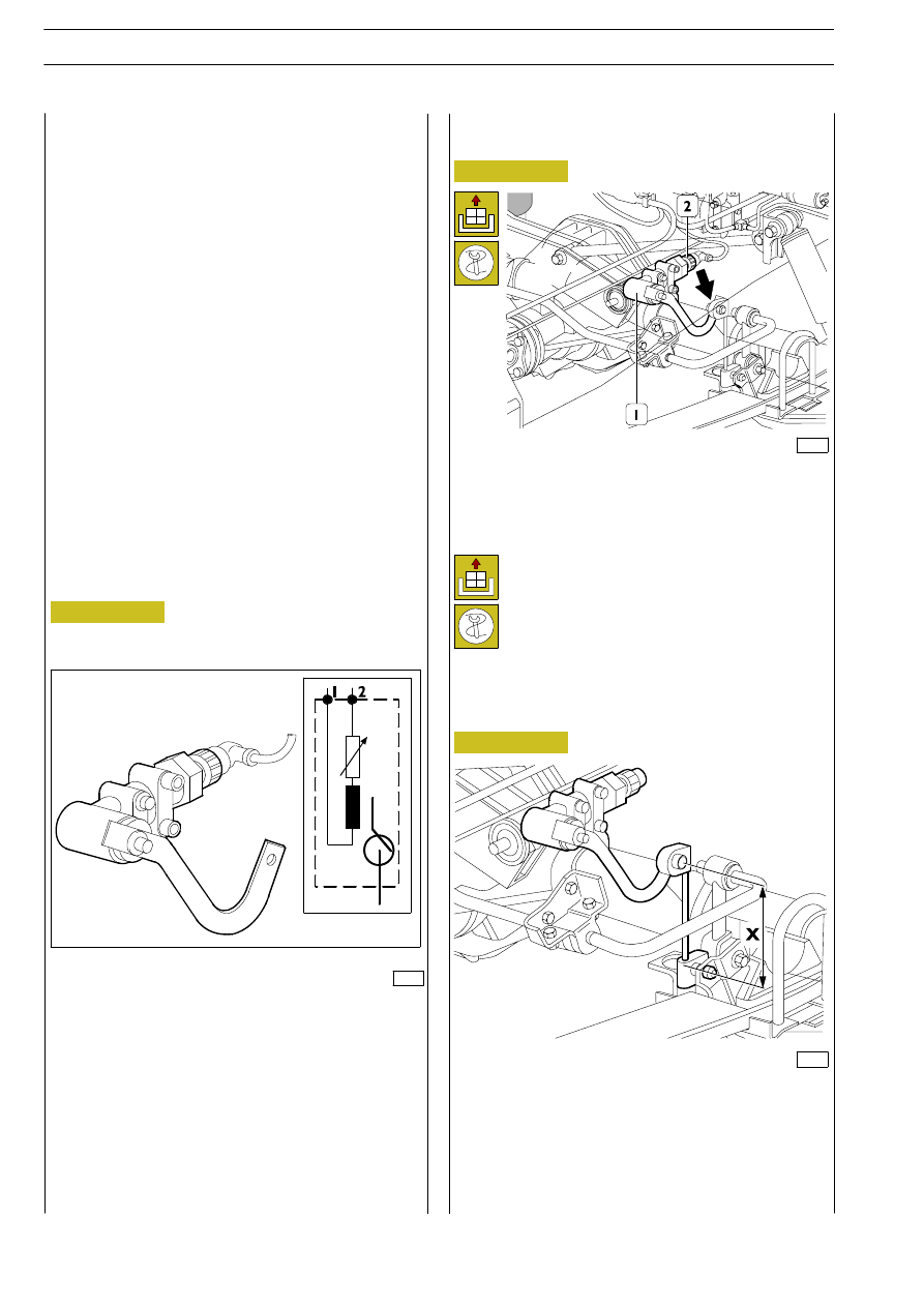
Disconnect the electrical connection (2), loosen the screw
(

⇒) and disconnect the levers. Loosen the fastening screws

and remove the level sensor (1).

62584

Operate on adjustment screws and set relay lever X value to
110 mm.

Perform ECU setting as shown in the relevant paragraphs
”ECU programming/setting”.

Figure 103

ECU programming/setting

WABCO ECU is not requiring programming since it is
supplied already programmed.

Setting can be performed by MODUS, E.A.SY. and IT2000
diagnostic systems and shall be performed when replacing the
following:

-

ECU;

-

level sensor;

-

level sensor levers.

Connect the diagnostic tool to the 38-pin socket and proceed
as follows to obtain correct setting:

-

check and adjust to 110 mm the level sensor lever length,
if required;

-

lift the chassis by depressing the proper video push
button (max. lifting);

-

Insert the special spacers provided (99346151) between
the chassis and the rear axle measuring 65 mm;

-

lower the chassis completely by depressing the proper
video push button (max.lowering);

-

set ECU by depressing the proper video push button.

62358

Level sensors inform constantly the ECU on distance changes
between chassis and road level.

Level sensors consists of a coil secured to the chassis and a
small piston.

When chassis height changes, a cam and a lever linked to the
axle make the piston move inside the coil, thus modifying its
inductance.

These changes will be used by the ECU in the different stages
of the system.

768822

LEVEL SENSOR

Figure 104

Figure 105

Level sensor replacement
Removal

Refitting

Reverse removal operations to perform refitting.

Perform level sensor and ECU setting as shown in the
relevant paragraphs ”ECU programming/setting” and
”Level sensor adjustment”.

Level sensor adjustment

Revi - February 2005

92

REAR AIR SUSPENSIONS

D

AILY

E

URO

62361

Vehicles not fitted with ABS/EBS/ABD systems have been
provided with the following components to obtain brakeforce
distribution:

-

double circuit load sensing valve;

-

load sensing valve pneumatic actuator.

The load sensing valve controls automatically the braking
torque produced by brakes on the rear axle, according to the
load applied on the rear axle, measured and transferred to the
load sensing valve of the pneumatic actuator.

The following diagram shows the brakeforce distribution ratio
corresponding to 0.15 as a function of pneumatic pressure
change inside air springs.

Figure 106

Air spring is an elastic element dedicated to contain pressure
air and to change its extension irrespectively of the applied
load.

62360

Position the vehicle on level ground.

Lift the rear part of the vehicle and rest the chassis on the
proper stands.

Use the hydraulic jack to support the rear axle.

Bleed the system and disconnect the air spring (3) supply pipe
(2).

Loosen upper (1) and lower fastening nuts.

Lower the rear axle and remove the air spring (3).

Air spring replacement
Removal

Figure 107

Figure 108

Figure 109

500731

AIR SPRING

Refitting

Reverse removal operations to perform refitting.

784310

LOAD SENSING VALVE

Legend

A

Hydraulic output pressure in bar;

B

Hydraulic control pressure in bar;

C

Pneumatic control pressure in bar;

D

Characteristic curves, 0.15 ratio (without load);

E

1:1 ratio (with load);

F

Pneumatic pressure/load characteristic curves.

62359

62362

REAR AIR SUSPENSIONS

93

D

AILY

E

URO

62578

- Loosen nut (1);
- apply 5 kg to plate (3) in point (2);
- start engine;
- disconnect the pneumatic actuator (4);
- with engine running at idle, depress the brake pedal

gradually until obtaining 100 bar pressure read on the
gauge set upstream connector. This value shall be constant
and shall be read on vehicle with load and without load;

- simulate the fully laden condition by lifting completely the

relay lever (3) and the unloaded condition by lowering the
lever completely;

- read output pressure value under both vehicle conditions

(laden and unloaded); obtained values shall comply with
those indicated on the plate, otherwise replace the load
sensing valve;

- operate the relay lever (3) to check whether the load

sensing valve piston is sliding smoothly into its seat,
otherwise replace the load sensing valve;

- reconnect the pneumatic actuator (4);
- load the vehicle to obtain 1500 kg weight on the rear axle

evenly distributed on the right and left side of the vehicle
with

± 5 kg tolerance;

- with engine running at idle and 100 bar pressure read on

the gauge set upstream the connector, check whether the
output pressure value read on the gauge set downstream
the connector is corresponding to the values indicated on
the plate, otherwise replace the load sensing valve;

- stop the vehicle, tighten nut (1) to the specified torque and

remove applied loads.

Figure 110

Bleed the system, loosen the screws (3) and disconnect the
pneumatic actuator (2).
Loosen the fastening screws of the load sensing valve (1) and
remove it including the pneumatic actuator (2).

Load sensing valve replacement
Removal

Figure 111

Figure 112

Refitting

Reverse removal operations to perform refitting.

Perform load sensing valve adjustment as shown in the
relevant paragraphs ”Load sensing valve adjustment
on vehicle”.

62433

Load sensing valve adjustment on vehicle

This device shall be checked and adjusted, if required, at
regular intervals by checking the values indicated on the plate
(Figure 111) located on the internal part of the engine hood.

!

Should the plate or the relevant technical data be
missing, ask the manufacturer for a duplicate
specifying the following:
- Vehicle type and wheelbase
- Rear axle weight
- Load sensing valve No.

Perform required operations in the following sequence:

- position the vehicle with the rear wheels set on the brake

test bed 99336914;

- connect gauges 99372269 or Modus to pressure control

intakes set upstream and downstream connector;

- should gauges not be fitted with valves for automatic

bleeding, bleed air by loosening the suitable ring nuts

!

Perform this check with gradually increasing pressure.

To check the load sensing valve, every braking system
component shall be in perfect operating conditions. When
replacing the leaf spring for special set-up, a new plate is
required with properly corrected values.

- when tests are over, check brake performance.

62577

LOAD SENSING VALVE PLATE

94

REAR AIR SUSPENSIONS

D

AILY

E

URO

62365

Figure 113

Position the vehicle on level ground. Lift the rear part of the
vehicle and rest the chassis on the proper stands. Use the
hydraulic jack to support the rear axle.
Bleed the system, remove the wheel, loosen the air spring
lower fastening screw (1). Loosen shock absorber lower
fastening nut (3) and disconnect it.
Loosen nuts (2) and remove the U bolts (4) and the elements
securing the leaf spring to the rear axle.
Loosen and remove the pin (6) and remove the leaf spring (5).

Figure 114

Figure 115

62363

500450

LEAF SPRING

Removal

500940

REAR SHOCK ABSORBERS

Removal

Lift the rear part of the vehicle and use the jack to support the
rear axle. Loosen the upper (3) and the lower (1) fastening
nuts and remove the shock absorber (2).

Refitting

Reverse removal operations to perform refitting.

Refitting

Reverse removal operations to perform refitting.

Refitting

Reverse removal operations to perform refitting.

528960

REAR STABILIZER BAR

Removal

62364

Operate on both vehicle sides.
Loosen the screws (1) and the nut (3). Remove the stabilizer
bar (4) including the joints (2).

REAR AIR SUSPENSIONS

95

D

AILY

E

URO

500730

REAR SUSPENSION OVERHAUL


Content   ..  187  188  189  190   ..