Iveco Daily Euro 4. Manual - part 178


  Index      Iveco     Iveco Daily Euro 4 - service repair manual 2006 year


Search            


Content   ..  176  177  178  179   ..


Iveco Daily Euro 4. Manual - part 178


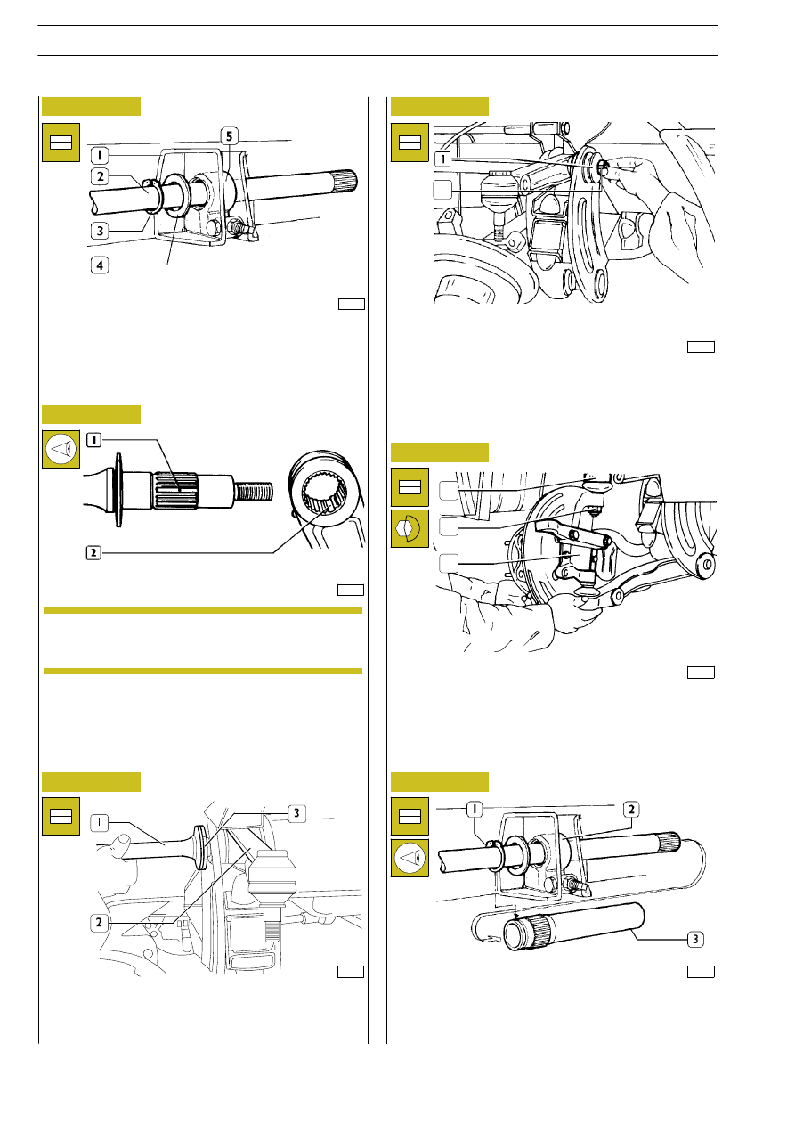
The splined part is provided with a double tooth (1), that shall
coincide at refitting with the double space (2) of the upper
lever.

62931

Set the upper lever (2) in the cross member, then insert the
torsion bar (1), including the washer (3), into cross member
and lever, making the double tooth coinciding with the
double space of the lever.

52370

19046

62928

Set the adjustment lever (5) in the bracket (1) and insert the
torsion bar (2) including the washer (4) and the circlip (3).

Figure 72

Figure 73

Figure 74

Figure 75

Fit the sleeve (3) on the torsion bar (1) and in the adjustment
lever (2) so that the marks on these components coincide as
shown in the following figure.

Set the washer (1) and screw the nut (2) without locking it.

The rear part of the torsion bars is marked with
AD-AS to identify respectively the right bar and
the left bar.

44674

Figure 76

Figure 77

44675

Connect the stub axle (3) to the upper lever (1) ball joint;
tighten the fastening nut (2) to the specified torque.

1

2

3

2

NOTE

48

FRONT MECHANICAL SUSPENSIONS

D

AILY

E

URO 4

62934

Figure 78

1. Bracket - 2. Adjustment lever - 3. Sleeve - 4. Torsion bar - 5. Washer - 6. Circlip - A. Front reference mark on sleeve (3)

- B. Front reference mark on adjustment lever (2) - C. Rear reference mark on sleeve (3) - D. Reference mark on torsion

bar (4) - E. Reference mark on left torsion bar - F. Reference mark on right torsion bar.

After refitting torsion bar (4)/ sleeve (3)/ adjustment lever (2), secure the sleeve (3) to the bracket with the circlip (6). Refit
the fuel tank (if removed).

AD. Right torsion bar

AS. Left torsion bar

FRONT MECHANICAL SUSPENSIONS

49

D

AILY

E

Torsion bar preload adjustment

TORSION BAR PRELOAD CHECK DIAGRAM

H = mm, height from ground of side member upper edge
measured as close as possible to suspension connection area
RSC (Loaded radius):
-

with 225/75R16 tyres, 345 mm with 2500 kg load

-

with 7.00R16 tyres, 364 mm with 2000 kg load

62935

Refit the tie rod (6) to the lever (3) without tightening to
torque the nut for screw (7); connect the articulated head
(4) of the steering box tie rod to the stub axle lever and
tighten the nut to the specified torque.

Connect the shock absorber with the screw (5) and the nut
(1) and tighten the latter to the specified torque.

Refit wheels, fit nut protection and tighten the fastening nuts;
remove stands and lower the vehicle.

Then tighten to the specified torque the following
components:

- wheel fastening nuts;
- nut and lock nut fastening the torsion bars to the

relevant levers;

- nuts for screws fastening the upper tie rods to the

relevant levers.

Adjust torsion bar preload as described in the following
paragraph.

Figure 79

Figure 80

Figure 81

If a different value is found, operate on the adjustment screw
(1) as required, taking into account that before performing
this operation the vehicle shall always be lifted from ground
with hydraulic jack to prevent screw damaging.

Once proper vehicle setup is obtained, lock the screw with
the lock nut (2).

62936

20986

Check whether tyre pressure is the specified one and then
using the proper gauge, check whether tyre tread depth is
almost the same on both wheels.

Measure on both vehicle sides the height (H) from ground
of side member upper edge - measured as close as possible
to suspension connection area

Height (H) shall correspond to the value specified in the
following table.

50

FRONT MECHANICAL SUSPENSIONS

D

AILY

E

URO 4

wheels

Tyres

wheels

(Kg)

225/75 R 16

7.00 R 16

1400

672

,0

691

,0

1500

665.6

684.6

1700

652.6

671.6

1800

646

,0

665

,0

1900

639.4

658.4

2100

626.1

645.1

2300

612.8

631.8

2400

606.1

625.1

2500

599.5

618.5

REAR MECHANICAL SUSPENSIONS

51

D

AILY

E

Rear mechanical suspensions

Page

DESCRIPTION

53

. . . . . . . . . . . . . . . . . . . . . . . . . .

CHARACTERISTICS AND DATA

54

. . . . . . . . . . .

- Rear leaf spring

54

. . . . . . . . . . . . . . . . . . . . . . . .

- Rear shock absorbers

71

. . . . . . . . . . . . . . . . . . . .

TOOLS

72

. . . . . . . . . . . . . . . . . . . . . . . . . . . . . . . .

TIGHTENING TORQUES

73

. . . . . . . . . . . . . . . . .

- Vehicles 29 L - 35 S

73

. . . . . . . . . . . . . . . . . . . . .

- Vehicles 35 C - 40 C - 45 C- 50 C

74

. . . . . . . . .

- Vehicles 60 C - 65 C

75

. . . . . . . . . . . . . . . . . . . .

REAR LEAF SPRING

76

. . . . . . . . . . . . . . . . . . . . . .

- Vehicles: 29 L - 35 S

76

. . . . . . . . . . . . . . . . . . . .

- Removal

76

. . . . . . . . . . . . . . . . . . . . . . . . . . . . . .

- Refitting

76

. . . . . . . . . . . . . . . . . . . . . . . . . . . . . .

- Vehicles: 35 C - 40 C - 45 C - 50 C -

60 C - 65 C

77

. . . . . . . . . . . . . . . . . . . . . . . . . . .

- Removal

77

. . . . . . . . . . . . . . . . . . . . . . . . . . . . . .

- Refitting

77

. . . . . . . . . . . . . . . . . . . . . . . . . . . . . .

REPAIRS

78

. . . . . . . . . . . . . . . . . . . . . . . . . . . . . . .

- Disassembling the leaf spring

78

. . . . . . . . . . . . . .

- Checks

78

. . . . . . . . . . . . . . . . . . . . . . . . . . . . . . .

- Assembling the leaf spring

78

. . . . . . . . . . . . . . . .

- Replacing the bushings

78

. . . . . . . . . . . . . . . . . . .

REAR SHOCK ABSORBERS

79

. . . . . . . . . . . . . . . .

- Removal

79

. . . . . . . . . . . . . . . . . . . . . . . . . . . . . .

- Refitting

79

. . . . . . . . . . . . . . . . . . . . . . . . . . . . . .

STABILIZER BAR

80

. . . . . . . . . . . . . . . . . . . . . . . . .

- Removal

80

. . . . . . . . . . . . . . . . . . . . . . . . . . . . . .

- Refitting

80

. . . . . . . . . . . . . . . . . . . . . . . . . . . . . .


Content   ..  176  177  178  179   ..