Iveco Daily Euro 4. Manual - part 162
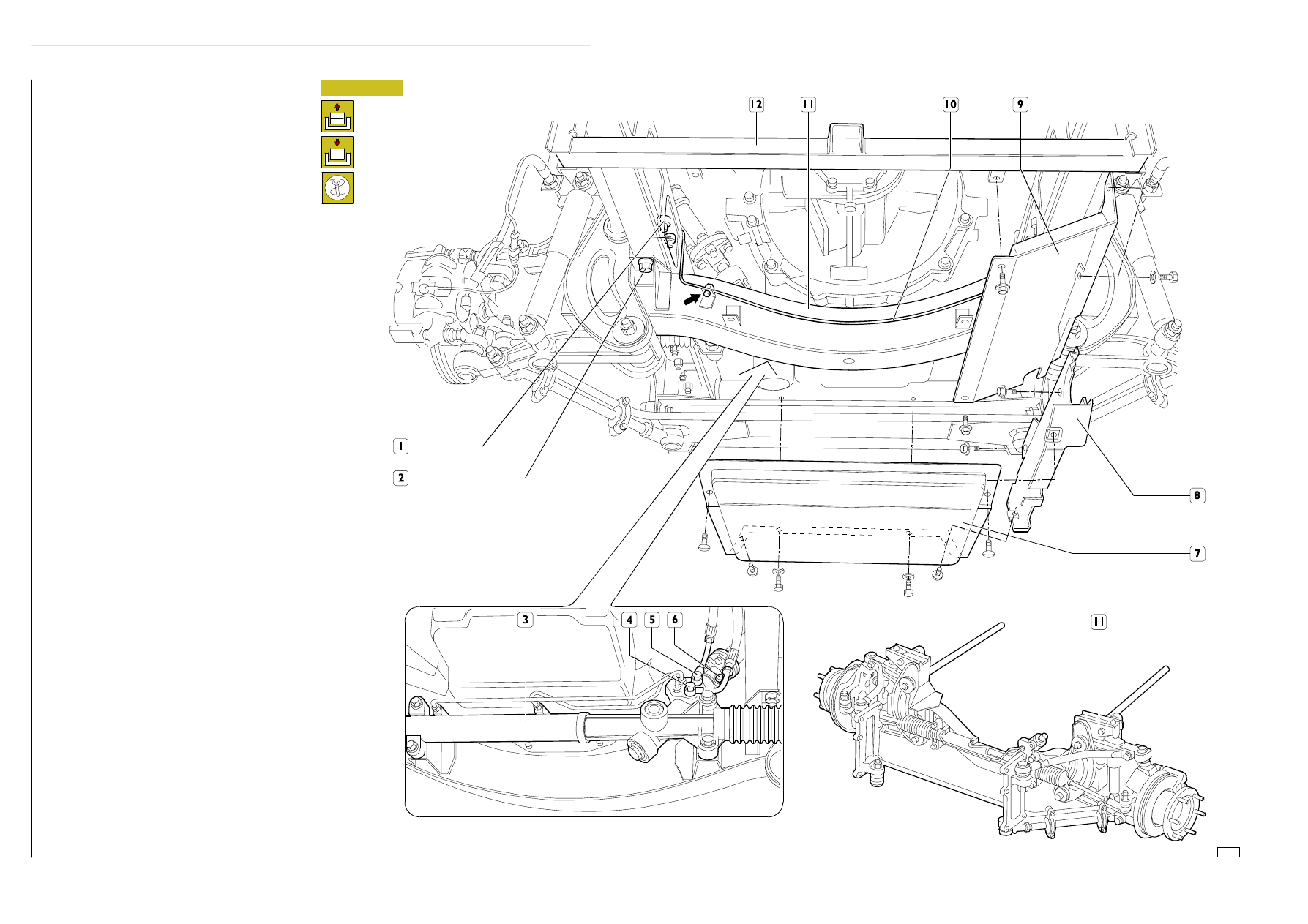
Figure 4
From underneath the vehicle:
- remove the central guard (7) under the engine by taking
out the screws securing it to the side guards (8) and to the
front cross member of the chassis frame;
- remove the right and left side guards (8) of the engine by
taking out the screws securing them to the chassis frame;
- remove the right and left side guards (9) of the gearbox by
taking out the screws securing them to the axle (11) and
to the cross member (12) under the gearbox;
- disconnect the brake fluid pipe (10) from the retaining
blocks on the axle;
- drain off the power-steering fluid and disconnect the pipes
(4) and (5);
- disconnect
the
power
steering
column
(3)
in
correspondence with the coupling (6);
- place the removal bracket on the hydraulic jack and put it
all under the axle;
- undo the chassis frame bottom fixing screws (2) and the
top fixing nuts (1);
- lower the hydraulic jack and extract the axle (11).
Refitting
Reverse the steps described for removal tightening the screws
or nuts to the prescribed torque.
Adjust the load of the torsion bar as illustrated under the
specific heading.
Top up the power-steering fluid.
If the brake callipers have been left on the axle, restore the
brake fluid level and bleed off any air.
Check and adjust the front wheel geometry.
75582
44
AXLE 5823
D
AILY
E
URO
4