Iveco Daily Euro 4. Manual - part 140


  Index      Iveco     Iveco Daily Euro 4 - service repair manual 2006 year


Search            


Content   ..  138  139  140  141   ..


Iveco Daily Euro 4. Manual - part 140


525031

Replacing the wheel hub bearing

44614

44616

44615

44617

44618

Figure 11

Figure 12

Figure 13

Figure 14

Figure 15

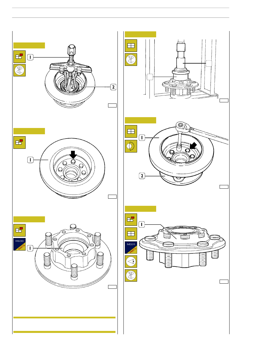
If the hub is fitted with a phonic wheel (2), take it out with
the extractor (1) 99341001 as shown in the figure.
Otherwise, take out the bearing guard ring.

Take out the screws (

⇒) and remove the brake disc (1) from

the wheel hub. Check the brake disc as described under the
Brakes heading.

The bearing (1) is removed from the wheel hub with the aid
of an ordinary punch.

Mount the brake disc (1) on the wheel hub (2) and tighten
the fixing screws (

⇒) to the required torque.

If it is necessary to replace the pins of the wheel hub (1),
before mounting the new ones, check that the mating surface
of the pin head is free from burrs, dross and blisters.

The pins should be driven in by applying a load on their head
no greater than 2000 kg.

After driving them home, check that the pins are perfectly in
touch with the hub: maximum orthogonal tolerance 0.2 mm.

Figure 16

45164

The new bearing should be mounted in the wheel hub with
a press and tool 99370498.

1

2

Bearing (1) driving load is 2100

÷ 5000 kg.

NOTE

68

REAR AXLE 450511

D

AILY

E

URO

4

44619

44620

44621

44622

Figure 17

Figure 18

Figure 19

Figure 20

Stand the bearing of the wheel hub (2) on a special mounting
that permits rotation. With a magnetic dial gauge (1) check
the off-centring of the brake disc on both sides.

Off-centring must not exceed 0.1 mm.

Check the orthogonality of the phonic wheel (2), proceeding
as follows:

Position the feeler of the magnetic dial gauge (1) on the
phonic wheel.

Making the wheel hub (3) turn, check that the maximum
error of orthogonality of the phonic wheel (2) is no greater
than 0.1 mm.

Mount the inserter 99370497 (2) on the sleeve.

Lubricate the sleeve with TUTELA W140/M-DA oil and key
the wheel hub (1).

Mount the washer (1) and a new ring nut (2). Using the
wrench 99355087 (3), tighten the ring nut (2) to the required
torque.
Notch the fixing ring nut (2) on the milling of the axle housing
arm.

Figure 21

The phonic wheel (2) should be mounted in the hub with the
punch 99370498 (1), checking after assembly that the
”phonic” wheel rests perfectly in its seat in the hub.

45165

1

2

Check and, if necessary, adjust the clearance
between the parking brake drum and shoes as
described in the Brakes section.

NOTE

REAR AXLE 450511

69

D

AILY

E

URO

Apply IVECO 1905685 sealant on the contact surfaces of the
drive shaft (2) with the wheel hub (1).

Mount the drive shaft (2) in the sleeve.

Tighten the screws (3) securing the drive shaft (2) to the hub
(1) to the required torque.

Fit new protection caps (3).
Connect the pipe (2) to the support bracket (1).

44623

101971

44611

101962

44626

Figure 22

Figure 23

Figure 24

Figure 25

Figure 26

Mount the support (2) and tighten the fixing screws (1) to
the required torque.

Mount braking pads (1).

Fit brake caliper (3) to support (2), then use torque wrench
(4) to tighten fastening screws (1) to a torque of 32 to 36
Nm.

!

Braking pad with wear signalling unit must be
mounted at brake caliper plunger side.

Having to move the brake caliper piston back, keep to the
instructions given in the BRAKES section.

!

Mount only new screws (1, Figure 24).

Every time they are removed, they must be replaced.

70

REAR AXLE 450511

D

AILY

E

URO

4

Mount a new O-ring on the differential locking attachment
plane.
Position the previously assembled support (3) so as to insert
the control lever in the spline on the sliding sleeve.
Insert the 4 screws (2) complete with washers and spring
washers and tighten the screws to the driving torque of 23
Nm (2.35 kgm).
Assemble the spring (1).
Adjust the differential locking device by following the
procedures below.

Remove gasket (4).
By means of a normal beater knock out the elastic pin (2),
remove the lever (1) complete with ring and washer.
Finally, remove the control lever (3) from the support (5).

Remove the spring (1).
Unscrew and remove the 4 screws (2) including washers and
then disconnect the differential locking device (3).
If required, remove the unit as described in the following
paragraphs.

61869

23227

61869

Figure 27

526210

DIFFERENTIAL REPAIR
OPERATIONS

526260

Disassembly of differential locking

Assemble the differential locking device by following the
removal operations in the reverse order.
Re-attach the differential locking device to the rear axle
casing as follows:

Assembling the differential locking device

Differential locking removal

Differential locking refitting

Figure 28

Figure 29

REAR AXLE 450511

71

D

AILY

E

URO


Content   ..  138  139  140  141   ..