Iveco Daily Euro 4. Manual - part 129
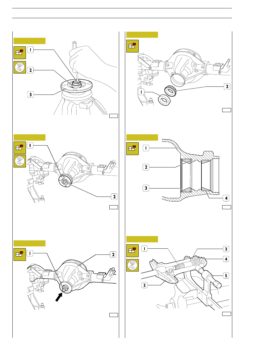
Lift denting (1) checking nut (2).
Using tool 99370317, stop the rotation of flange (3).
Unscrew and remove nut (2).
108047
108049
108048
108050
107839
74727
Figure 26
Figure 27
Figure 28
Figure 29
Figure 30
Figure 31
Take flange (1) out of bevel pinion (2).
Should flange (2) be too difficult to remove, single-acting rear
axle 99341003 coupled to bracket pair 99341009 can be
used as an extracting assembly.
Using a proper beater, beat according to direction indicated
by the arrow until bevel pinion (1) complete with rear
bearing, fixed spacer and adjusting nut is ejected from rear
axle box (2).
Remove the seal (1) and the internal ring (2) of the front
bearing.
Use a punch to remove the external rings (3 - 4) of the
tapered roller bearings from the axle housing (1) and take out
the adjustment shim (2).
With axle 99341003 (2), brackets 99341011 (1), press
99341015 (5) extract the internal ring (3) on the bevel pinion
(4).
Dismounting bevel pinion
24
REAR AXLE NDA RS
D
AILY
E
URO
4