Iveco Daily Euro 4. Manual - part 44


  Index      Iveco     Iveco Daily Euro 4 - service repair manual 2006 year


Search            


Content   ..  42  43  44  45   ..


Iveco Daily Euro 4. Manual - part 44


102201

Place the vehicle in a pit or on an auto lift.
Remove, from under the vehicle, the central sound-proofing
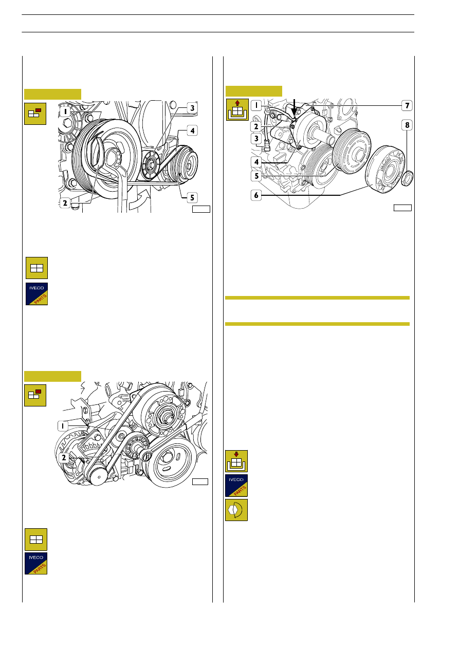
guard. Remove elastic belt (4) from pulleys (1 and 5).

543910

REPLACING

AIR-CONDITIONING

COMPRESSOR DRIVE BELT

102202

Drain the cooling fluid, and then remove both the front
cross-member and the radiator, as described in the “Power
unit detachment/re-attachment” chapter.
Take the fan off the electro-magnetic joint.
Remove electric connection (3) from the engine cable.
Stop rotation of electro-magnetic joint (6), then remove nut
(8).

Re-attachment is carried out by reversing the order
of detachment operations. In particular, tighten the
screws and nuts to the specified torque values.

After re-attachment has been completed, fill the
engine cooling system, start the engine and check for
cooling fluid leaks.

Assembly

Apply wedge 99360161 (2) with elastic belt (4) to
pulley (1), then place the elastic belt onto roller (3)
and pulley (5), taking care to place the pulley ribs in
the corresponding races of pulleys (1 and 5).

543910

POWER STEERING PUMP-ALTER-
NATOR BELT REPLACEMENT

Disassembly

Disassemble the compressor drive belt, if there is one, as
described under the relevant heading.
Slacken off the tension of the belt (1) using a specific wrench
on the automatic tightener (2) and remove the belt.

Assembly

Mount the drive belt (1) taking care to position its
ribs correctly in the respective races of the pulleys.
Release the automatic tightener (2). Turn the
crankshaft by one turn to settle the belt.

543210

REPLACING THE WATER PUMP

Removal

Unscrew nut (8) in a clockwise direction, since the
nut thread goes leftwards.

Take off hub (6) and pulley (5).
Cut the strap (

→), remove electric cable (3) retaining strap

fastening

screw

(1),

remove

nuts

(2),

then

take

electro-magnet (4) off water pump (7).
Remove the fastening screws, and then take off water pump
(7).

Refitting

NOTE

88330

Rotate the drive shaft counterclockwise (

→) until belt (4) is

correctly coupled with pulley (1).

Mount the compressor drive belt, if there is one, and adjust
the tension as described under the relevant heading.
Fit the middle soundproofing guard back on.

Figure 5

Figure 6

Figure 7

Disassembly

168

F1C ENGINE

D

AILY

E

URO

4

Remove cap (2), then take cover (1) off the cylinder head.
Loosen the straps, then disconnect air pipe (3) from the inlet
manifold and the heat exchanger.
Use tool 99360076 to take oil filter (4) off the heat
exchanger.
Remove the electric connection from pressure regulator
(13).
Remove

connections (8

and 10), then disconnect

low-pressure pipes (11) from high-pressure pump (9).
Remove pipe (5) retaining bracket (7) fastening screw (6),
then disconnect the retaining bracket from hydraulic
accumulator (14) and high-pressure pump (9).
Remove screws (18) and spacers (19), then remove
high-pressure pump (9) from support (15). Remove joint
(16).

771010

REPLACING THE HIGH-PRESSURE PUMP

Removal

108635

Re-attachment is carried out by reversing the order
of detachment operations. In particular, comply with
the following instructions:

- replace the seal rings, gaskets, high-pressure pipe

and oil filter with new parts;

- lubricate, prior to assembling, seal ring (17) with

engine oil;

- tighten the screws, nuts, fittings and oil filter to

the specified torque value;

- check the engine oil level; top up, if necessary.

Refitting

Figure 8

F1C ENGINE

169

D

AILY

E

URO

102204

Remove oil filling plug (1) from oil tank (2).
Remove, from under the engine compartment, the central
sound-proofing guard.
Place a container under power steering pump (6) to recover
the oil from the system, and then remove fittings (3 and 8)
and disconnect oil pipes (4 and 7) from power steering pump
(6).

501450 REPLACING THE POWER STEE-

RING PUMP

Removal

102207

Use tool 99360190 (3) to stop drive shaft rotation, then
remove screw (2) and take off damper pulley (1).

Apply tool 99340059 (6) as shown in the figure to remove
seal ring (5) from cover (4).

102205

Remove screws (6) and take power steering pump (5) off
support (4). Remove joint (2) from drive arbor (3).

Re-attachment is carried out by reversing the order
of detachment operations. In particular, take care of
the following:
- replace seal ring (1) with a new part, and

lubricate the same with engine oil prior to
assembling;

- replace the oil pipe gaskets (as above);
- tighten the nuts, screws and fittings to the

specified torque values.

After re-attachment has been completed, fill the
hydraulic power steering circuit and bleed the air as
described under the relevant heading.

Refitting

540440 REPLACING THE DRIVE SHAFT

SEAL RING AND THE FRONT
COVER GASKET

Removal

102206

Proceed as follows, by operating as described in the “Power
unit detachment/re-attachment” chapter:
- drain the engine cooling fluid;
- remove the front cross-member;
- remove the radiator.
Remove fan (1) from the electro-magnetic joint.
Take off the air-conditioning compressor drive belt (if any)
as well as the water pump-alternator drive belt, as described
in the relevant chapters.

Figure 9

Figure 10

Figure 11

Figure 12

170

F1C ENGINE

D

AILY

E

URO

4

102209

Remove screw (11), and then take off dipstick pipe (4).
Loosen strap (3), remove screw (2), then take pipe (1) off
cover (5).
Remove screws (6), and then take off cover (5). Remove
snap ring (8). Take out centrifugal filter (7).

102216

Fit cover (1) centring tool 99396030 (3) into the centrifugal
filter seat, then tighten screws (2) to the specified torque.
Remove tools 99346258 (4) and 99396039 (3).

102214

Mount cover (1) with a new gasket. Screw down screws (2)
without tightening them up.

Refitting

102215

Thoroughly clean cover (1) seal ring seat.
Screw down part (2) of tool 99346258 into the drive shaft
shank.
Lubricate the drive shaft shank and the outside of part (2),
then couple the new seal ring (3) with part (2).
Place part (4) onto part (2), screw down nut (5) until seal ring
(3) is fully assembled to cover (1).

Both centrifugal filter (7) and cover seal ring (5)
must be replaced every time they are dismounted.

Remove screws (9), and then take off front cover (10).

NOTE

Figure 13

Figure 14

Figure 15

Figure 16

F1C ENGINE

171

D

AILY

E

URO


Content   ..  42  43  44  45   ..