Engines Iveco C87 / Cursor 87. Manual - part 5


  Index      Iveco     Engines Iveco C87 / Cursor 87 (CURSOR TIER 3 SERIES) - service repair manual 2007 year


Search            


Content   ..  3  4  5  6   ..


Engines Iveco C87 / Cursor 87. Manual - part 5


115877

115876

115878

115879

Figure 15

Figure 16

Figure 17

Figure 18

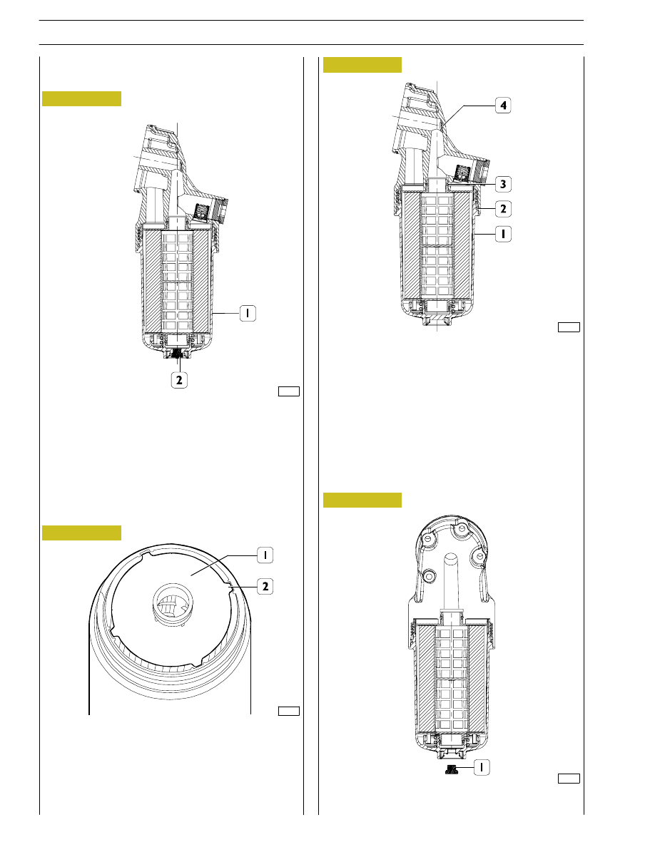
Replacing oil filter cartridge

Dismantling

Remove the plug (2).

Undo the filter casing (1) by a couple of turns and wait for
a few minutes.

In this way the remaining oil in the casing starts firstly to drip
and then to flow smoothly out.

Completely undo the casing and then replace the cartridge.

Insert the cartridge in the casing aligning the centering tabs
(2) on the upper plate (1) with the seats.

The cartridge should be pushed into the container until the
action of the attachment system at the bottom of the casing
is overcome.

At the same time, the tabs on the upper plate should slide
into the housings.

Move the upper part of the casing thread close to the first
lower thread of the support (the cartridge cover element
should be in contact with the oil outlet duct on the support.

Proceed with tightening the cartridge-casing assembly (1) on
the support (4).

During this stage both the seal (3) for the oil outlet
duct-cartridge element and the casing-support seal (2) will
gradually be involved.

Tighten the filter casing to a torque of 65 Nm.

Tighten the protective cap (1) on the filter casing.

Refitting

12

SECTION 1 - GENERAL SPECIFICATIONS

F2C CURSOR ENGINES

Base - June 2006

114248

Figure 19

Oil fume recycle (Blow-by)

Part of gas produced by combustion during engine operation leaks through piston elastic ring openings into sump, mixing with
oil fumes in sump.

This mixture, conveyed upward, is partially separated from oil by a device located in timing cover upper part and introduced in
air intake circuit.

The device mainly consists of a rotary filter secured on propeller shaft and by a front cover housing normally closed valves
controlling mixture flow.

Gas with oil contents greater than 10 g/h

Gas with oil contents approx. 0,2 g/h

Condensed oil returning to oil sump

SECTION 1 - GENERAL SPECIFICATIONS

13

F2C CURSOR ENGINES

COOLING

Description

The engine cooling system is of the closed-circuit, forced circulation type.
It consists mainly of the following components:

- expansion tank, not supplied (by FPT);

- a heat exchanger to cool down lubrication oil;

- a water pump with centrifugal system incorporated in the cylinder block;

- fan, not supplied;

- a 2-way thermostat controlling the coolant circulation.

Operation

The water pump is actuated by the crankshaft through a poli-V belt and sends coolant to the cylinder block, especially to the
cylinder head (bigger quantity). When the coolant temperature reaches and overcomes the operating temperature, the
thermostat is opened and from here the coolant flows into the radiator and is cooled down by the fan.
The pressure inside the system, due to temperature change, is adequately controlled through the expansion vessel.

14

SECTION 1 - GENERAL SPECIFICATIONS

F2C CURSOR ENGINES

Base - June 2006

Figure 20

114249

Water flowing out of the thermostat

Water circulating in the engine

Water flowing into the pump

SECTION 1 - GENERAL SPECIFICATIONS

15

F2C CURSOR ENGINES


Content   ..  3  4  5  6   ..