Isuzu Amigo / Axiom / Trooper / Rodeo / VehiCross. Manual - part 547


  Index      Isuzu     Isuzu Amigo / Axiom / Trooper / Rodeo / VehiCross - service repair manual 1999-2002 year


Search            


Content   ..  545  546  547  548   ..


Isuzu Amigo / Axiom / Trooper / Rodeo / VehiCross. Manual - part 547


1A–56 HEATING, VENTILATION AND AIR CONDITIONING (HVAC)

Compressor Assembly

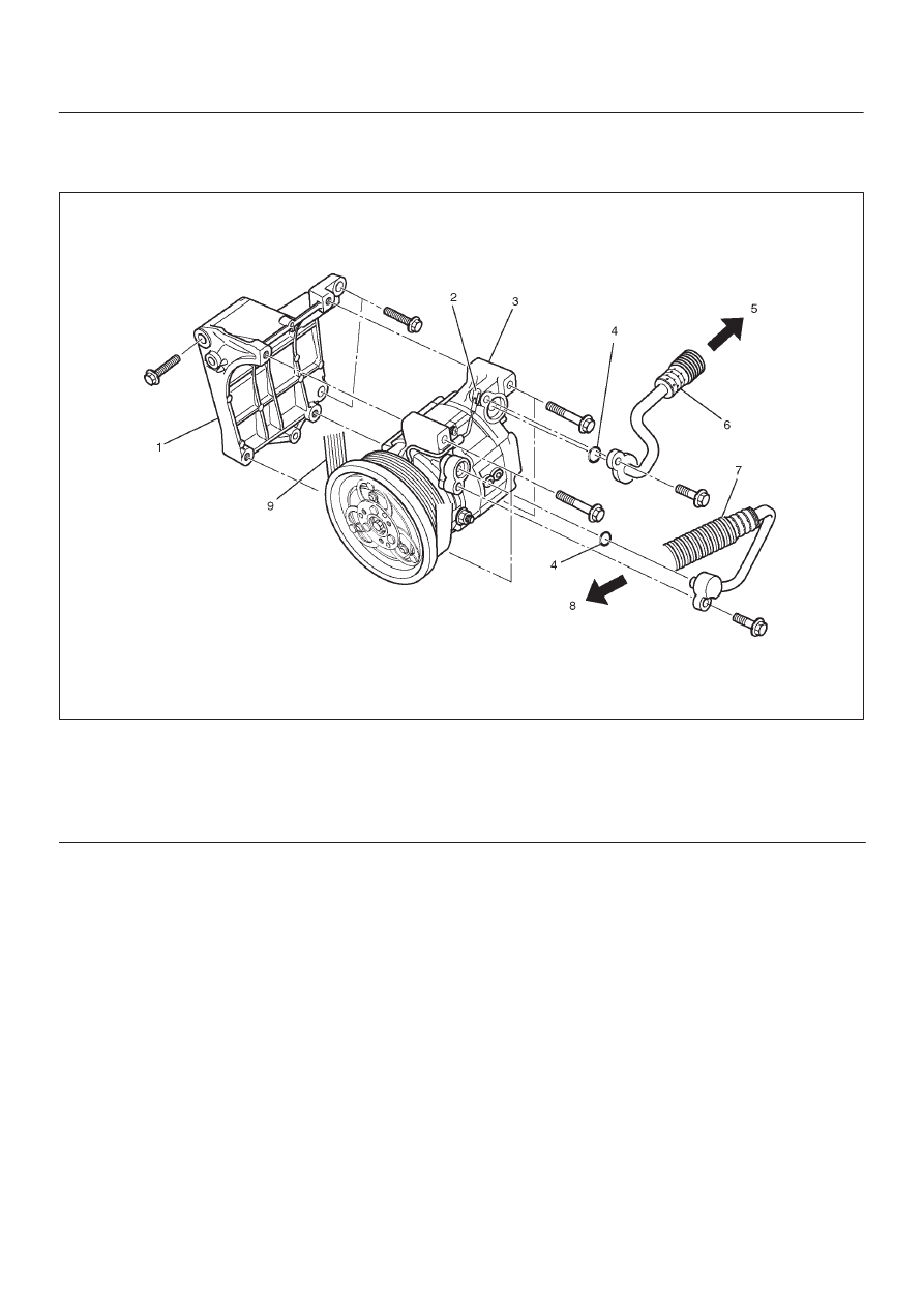
Compressor Assembly and Associated Parts (6VE1)

852R200013

Legend

(1) Compressor Bracket
(2) Magnetic Clutch Harness Connector
(3) Compressor
(4) O-ring

(5) To Evaporator
(6) Suction Line (Low-Pressure Hose)
(7) Discharge Line (High-Pressure Hose)
(8) To Condenser
(9) Serpentine Belt

Removal

1. Disconnect the battery ground cable.
2. Discharge and recover refrigerant

D

Refer to Refrigerant Recovery in this section.

3. Disconnect magnetic clutch harness connector.

HEATING, VENTILATION AND AIR CONDITIONING (HVAC) 1A–57

4. Remove serpentine belt.

D

Move serpentine belt tensioner to loose side using
wrench then remove serpentine belt.

850R200001

Legend

(1) Auto Tensioner
(2) Idle Pulley
(3) Cooling Fan Pulley
(4) Serpentine Belt
(5) Power Steering Oil Pump
(6) Air Conditioner Compressor
(7) Crankshaft Pulley
(8) Generator

5. Disconnect refrigerant line connector.

D

When removing the line connector, the connecting
part should immediately be plugged or capped to
prevent foreign matter from being mixed into the
line.

6. Remove compressor.

Installation

1. Install compressor.

D

Tighten the compressor fixing bolts to the specified
torque.

Torque: 19 N

m (14 lb

ft)

2. Connect refrigerant line connector.

D

Tighten the refrigerant line connector fixing bolts to
the specified torque.

Torque: 15 N

m (11 lb

ft)

D

O-rings cannot be reused. Always replace with new
ones.

D

Be sure to apply new compressor oil to the O-rings
when connecting refrigerant lines.

3. Install serpentine belt.

D

Move serpentine belt tensioner to loose side using
wrench, then install serpentine belt to normal
position.

4. Connect magnetic clutch harness connector.

New Compressor Installation

The new compressor is filled with 150cm

3

 (5.0fl.oz.)of

compressor oil and nitrogen gas. When mounting the
compressor on the vehicle, perform the following steps;

1. Gently release nitrogen gas from the new

compressor.

D

Take care not to let the compressor oil flow out.

D

Inspect O-rings and replace if necessary.

871R200003

2. Turn the compressor several times by hand and

release the compressor oil in the rotor.

3. When installing on a new system, the compressor

should installed as it is. When installing on a used
system, the compressor should be installed after
adjusting the amount of compressor oil. (Refer to
Compressor in this section)

871R200004

1A–58 HEATING, VENTILATION AND AIR CONDITIONING (HVAC)

Condenser Assembly

Condenser Assembly and Associated Parts

875R200027

Legend

(1) Refrigerant Line
(2) Pressure Switch Connector
(3) Front Bumper Assembly

(4) Radiator Grille
(5) Engine Hood Front End Stay
(6) Condenser Assembly

Removal

1. Disconnect the battery ground cable.
2. Discharge and recover refrigerant.

D

Refer to Refrigerant Recovery in this section.

3. Remove radiator grille.
4. Remove front bumper assembly.

D

Refer to Bumpers in Body and Accessories section.

5. Remove engine hood front end stay.
6. Disconnect pressure switch connector.
7. Disconnect refrigerant line.

D

When removing the line connector, the connecting
part should immediately be plugged or capped to
prevent foreign matter from being mixed into the
line.

8. Remove condenser assembly.

D

Handle with care to prevent damaging the
condenser or radiator fin.

Installation

1. Install condenser assembly.

D

If installing a new condenser, be sure to add 30cm

3

(1.0 fl. oz.) of new compressor oil to a new one.

D

Tighten the condenser fixing bolts to the specified
torque.

Torque: 6 N

m (52 lb

in)

2. Connect refrigerant line.

D

Tighten the inlet line connector fixing bolt to the
specified torque.

Torque: 15 N

m (11 lb

ft)

D

Tighten the outlet line connector fixing bolt to the
specified torque.

Torque: 6 N

m (52 lb

in)

D

O-rings cannot be reused. Always replace with new
ones.

HEATING, VENTILATION AND AIR CONDITIONING (HVAC) 1A–59

D

Be sure to apply new compressor oil to the O-rings
when connecting the refrigerant line.

3. Connect pressure switch connector.

4. Install engine hood front end stay.
5. Install front bumper assembly.
6. Install radiator grille.

Receiver / Drier

Receiver / Drier and Associated Parts

875R200034

Legend

(1) Pressure Switch Connector
(2) Refrigerant Line

(3) Radiator Grille
(4) Receiver / Drier

Removal

1. Disconnect the battery ground cable.
2. Discharge and recover refrigerant.

D

Refer to Refrigerant Recovery in this section.

3. Remove radiator grille.
4. Disconnect pressure switch connector.
5. Disconnect refrigerant line.

D

When removing the line connected part, the
connecting part should immediately be plugged or
capped to prevent foreign matter from being mixed
into the line.

6. Remove receiver/drier.

D

Loosen the bolt, then, using care not to touch or
bend the refrigerant line, carefully pull out the
receiver/drier.

Installation

To install, follow the removal steps in the reverse order,
noting the following points:

1. If installing a new receiver/drier, be sure to add 30cm

3

(1.0 fl. oz.) of new compressor oil to a new one.

2. Put the receiver/drier in the bracket and connect with

the refrigerant line.  Check that no excessive force is
imposed on the line.  Fasten the bracket bolt to the
receiver/drier.

3. Tighten the refrigerant line to the specified torque.

Torque: 6 N

m (52 lb

in)

4. O-rings cannot be reused. Always replace with new

ones.

5. Be sure to apply new compressor oil to the O-rings

when connecting the refrigerant line.


Content   ..  545  546  547  548   ..