Content .. 1039 1040 1041 1042 ..
Isuzu Amigo / Axiom / Trooper / Rodeo / VehiCross. Manual - part 1041
SUPPLEMENTAL RESTRAINT SYSTEM
9J–5
1. Energy Reserve — The SDM maintains 24–Volt Loop
Reserve (24VLR) energy supply to provide
deployment energy when ignition voltage is lost in a
frontal crash.
2. Frontal Crash Detection — The SDM monitors
vehicle velocity changes to detect frontal crashes
which are severe enough to warrant deployment.
3. Air Bag Deployment — When a frontal crash of
sufficient force is detected, the SDM will cause
enough current to flow through the air bag assembly
to deploy the air bag.
4. Malfunction Detection — The SDM performs
diagnostic monitoring of SRS electrical components
and sets a diagnostic trouble code when a
malfunction is detected.
5. Frontal Crash Recording — The SDM records
information regarding SRS status during frontal
crash.
6. Malfunction Diagnosis — The SDM displays SRS
diagnostic trouble codes and system status
information through the use of a scan tool.
7. Driver Notification — The SDM warns the vehicle
driver of SRS malfunctions by controlling the “Air
Bag” warning lamp.
The SDM is connected to the SRS wiring harness by a
24–pin connector. This harness connector uses a
shorting clip across certain terminals in the contact area.
This shorting clip connects the “AIR BAG” warning lamp
to ground when the SDM harness connector is
disconnected or CPA (Connector Position Assurance) is
not inserted even if completely connected. This will
cause the “AIR BAG” warning lamp to come “ON” steady
whenever the ignition switch is at the ON or START
positions with the SDM disconnected.
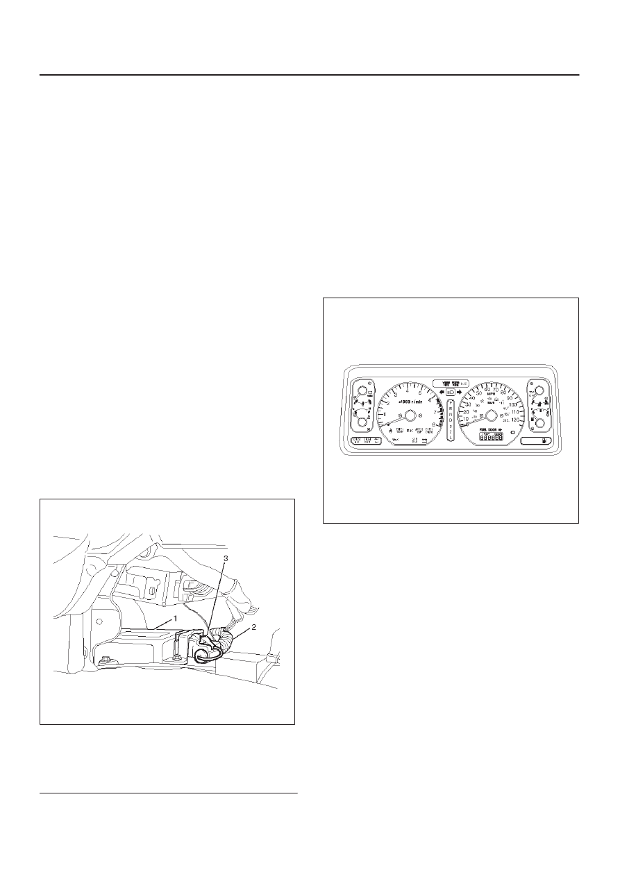
827RW004
Legend
(1) SDM
(2) SRS Harness
(3) Connector Position Assurance
“Air Bag” Warning Lamp
Ignition voltage is applied to the “AIR BAG” warning lamp
when the ignition switch is at the ON or START positions.
The SDM controls the lamp by providing ground with a
lamp driver. The “AIR BAG” warning lamp is used in the
SRS to do the following:
1. Verify lamp and SDM operation by flashing SEVEN
(7) times when the ignition switch is first turned “ON”.
2. Warn the vehicle driver of SRS electrical system
malfunctions which could potentially affect the
operation of the SRS. These malfunctions could
result in nondeployment in case of a frontal crash or
deployment for conditions less severe than intended.
The “AIR BAG ” warning lamp is the key to driver
notification of SRS malfunctions. For proper lamp
operation, refer to the “SRS Diagnostic System Check” in
this section.
821RW037
SRS Coil Assembly
The SRS coil assembly consists of two current carrying
coils. This is attached to the steering column and allow
rotation of the steering wheel while maintaining
continuous contact of the driver deployment loop to the
driver air bag assembly.
There is a shorting clip on the yellow 2–pin connector near
the base of steering column which connects the SRS coil
to the SRS wiring harness.
The shorting clip shorts to the SRS coil and driver air bag
assembly when the yellow 2–pin connector is
disconnected. The circuit to the driver air bag assembly is
shorted in this way to help prevent unwanted deployment
of the air bag when servicing the steering column or other
SRS components.