Isuzu Amigo / Axiom / Trooper / Rodeo / VehiCross. Manual - part 69


  Index      Isuzu     Isuzu Amigo / Axiom / Trooper / Rodeo / VehiCross - service repair manual 1999-2002 year


Search            


Content   ..  67  68  69  70   ..


Isuzu Amigo / Axiom / Trooper / Rodeo / VehiCross. Manual - part 69


WHEEL AND TIRE SYSTEM

3E–11

Wheel

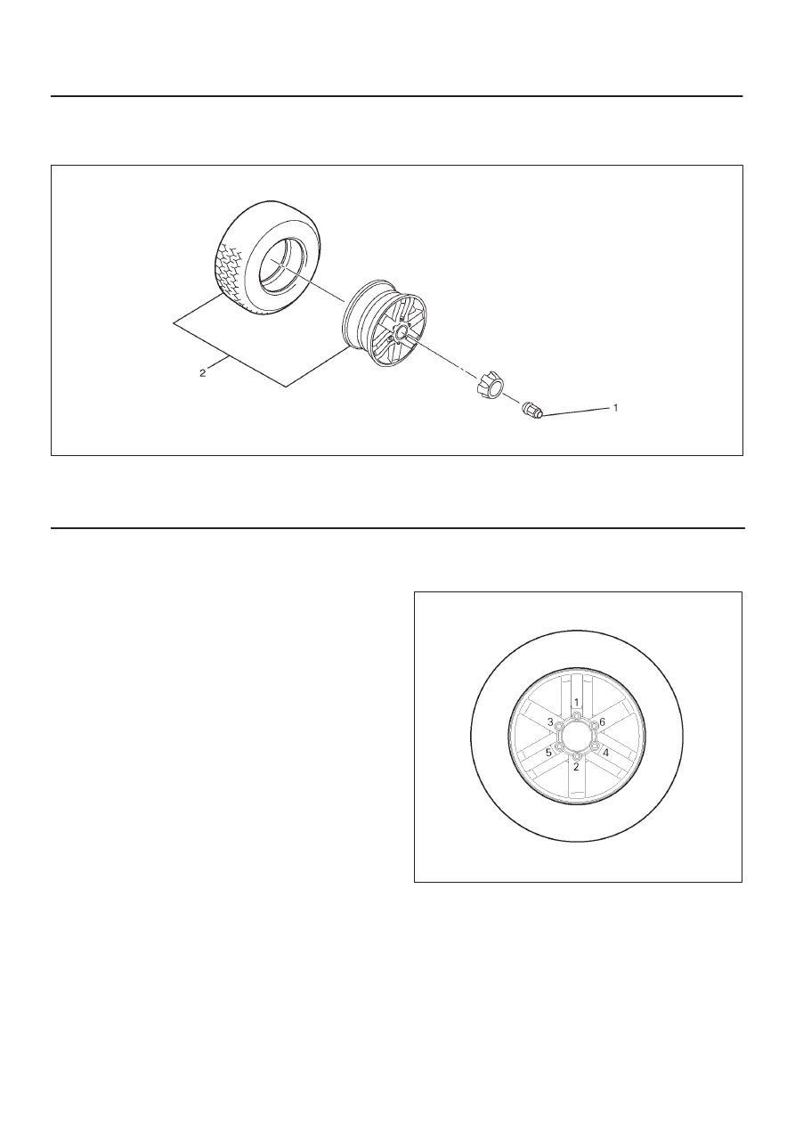
Wheel and Associated Parts

480R200004

Legend

(1) Wheel Lug Nut
(2) Alumi Wheel and Tire

Removal

1. Loosen wheel lug nut by approximately 180

°

 (half a

rotation), then raise the vehicle and remove the nuts.

2. Remove wheel and tire.

NOTE: Never use heat to loosen a tight wheel lug nut.
The application of heat to the hub can shorten the life of
the wheel and may cause damage to wheel bearings.

Installation

1. Install wheel and tire.
2. Install wheel lug nut, and lower the vehicle. Tighten

the wheel lug nuts to the specified torque in numerical
order.

Torque: 118 N·m (87 lb ft)

CAUTION: Before installing wheels, remove any
build-up of corrosion on the wheel mounting surface
and brake disc mounting surface by scraping and
wire brushing.  Installing wheels without good
metal-to-metal contact at mounting surfaces can
cause wheel nuts to loosen, which can later allow a
wheel to come off while the vehicle is moving.

NOTE: Valve caps should be on the valve stems to keep
dust and water out.

480R200003

3E–12

WHEEL AND TIRE SYSTEM

Tire

Tire Replacement

When replacement is necessary, the original metric tire
size should be used.  Most metric tire sizes do not have
exact corresponding alphanumeric tire sizes.  It is
recommended that new tires be installed in pairs on the
same axle.  If necessary to replace only one tire, it should
be paired with tire having the most tread, to equalize
braking traction.

CAUTION: Do not mix different types of tires such
as radial, bias and bias-belted tires except in
emergencies, because vehicle handling may be
seriously affected and may result in loss of control.

Tire Dismounting

Remove valve cap on valve step and deflate the tire. Then
use a tire changing machine to mount or dismount tires.
Follow the equipment manufacturer’s instruction.  Do not
use hand tools or tire lever alone to change tires as they
may damage the tire beads or wheel rim.

Tire Mounting

Rim bead seats should be cleaned with a wire brush or
coarse steel wool to remove lubricants, and light rust.
Before mounting a tire, the bead area should be well
lubricated with an approved tire lubricant.
After mounting, inflate the tire to 196kPa (28 psi) so that
beads are completely seated.  Inflate the air to specified
pressure and install valve cap to the stem.

WARNING: NEVER STAND OVER TIRE WHEN
INFLATING. BEAD MAY BREAK WHEN BEAD SNAPS
OVER RIM’S SAFETY HUMP AND CAUSE SERIOUS
PERSONAL INJURY.

NEVER EXCEED 240 KPA (35 PSI) PRESSURE WHEN
INFLATING. IF 240 KPA (35 PSI) PRESSURE WILL
NOT SEAT BEADS, DEFLATE, RE-LUBRICATE AND
RE-INFLATE. OVER INFLATION MAY CAUSE THE
BEAD TO BREAK AND CAUSE SERIOUS PERSONAL
INJURY.

Tire Repair

There are many different materials on the market used to
repair tires.
Manufacturers have published detailed instructions on
how and when to repair tires.  These instructions can be
obtained from the tire manufacturer if they are not
included with the repair kit.

Wheel Inspection

Damaged wheels and wheels with excessive run-out
must be replaced.
Wheel run out at rim (Base on hub Bore):

Aluminum
1– Vertical play: Less than 0.55 mm (0.022 in)
2– Horizontal play: Less than 0.55 mm (0.022 in)

480RS012

General Balance Procedure

Deposits of mud, etc. must be cleaned from the inside of
the rim.
The tire should be inspected for the following: match
mount paint marks, bent rims, bulges, irregular tire wear,
proper wheel size and inflation pressure.  Then balance
according to the equipment manufacturer’s
recommendations.
There are two types of wheel and tire balance.
Static balance is the equal distribution of weight around
the wheel.
Assemblies that are statically unbalanced cause a
bouncing action called tramp. This condition will
eventually cause uneven tire wear.

WHEEL AND TIRE SYSTEM

3E–13

480RS013

Legend

(1) Heavy Spot Wheel Shimmy
(2) Add Balance Weights Here

Dynamic balance is the equal distribution of weight on
each side of the wheel center-line so that when the tire
spins there is no tendency for the assembly to move from
side to side.  Assemblies that are dynamically unbalanced
may cause shimmy.

480RS014

Legend

(1) Heavy Spot Wheel Hop
(2) Add Balance Weights Here

WARNING: STONES SHOULD BE REMOVED FROM
THE TREAD TO AVOID OPERATOR INJURY DURING
SPIN BALANCING AND TO OBTAIN A GOOD
BALANCE.

Balancing Wheel and Tire

On-vehicle Balancing

On-Vehicle balancing methods vary with equipment and
tool manufacturers.  Be sure to follow each
manufacturer’s instructions during balancing operation.

Off-vehicle Balancing

Most electronic off-vehicle balancers are more accurate
than the on-vehicle spin balancers.  They are easy to use
and give a dynamic balance.  Although they do not correct
for drum or disc unbalance (as on- vehicle spin balancing
does), they are very accurate.

480RS015

3E–14

WHEEL AND TIRE SYSTEM

Main Data and Specifications

General Specifications

Wheels

Size

17 

×

 7JJ

Offset

38.0 mm (1.50 in)

P.C.D., wheel studs

139.7 mm (5.50 in)

Standard tire

Size

P235/65R17

Pressure(Front)

180 kPa (26 psi)

Pressure(Rear)

180 kPa (26 psi)

Torque Specifications

480R200005


Content   ..  67  68  69  70   ..