Isuzu Amigo / Axiom / Trooper / Rodeo / VehiCross. Manual - part 27


  Index      Isuzu     Isuzu Amigo / Axiom / Trooper / Rodeo / VehiCross - service repair manual 1999-2002 year


Search            


Content   ..  25  26  27  28   ..


Isuzu Amigo / Axiom / Trooper / Rodeo / VehiCross. Manual - part 27


HEATING, VENTILATION AND AIR CONDITIONING (HVAC) 1A–79

Actuator

The actuators are power driven type containing a small
motor.  Receiving output current from the automatic air
conditioner control unit, actuators drive the heater and
blower unit mode doors.
Actuators consist of the mode actuator used for switching
the mode (blow port selection), the mix actuator used for
changing aperture of the air mix door, the intake actuator
used for switching the intake mode(fresh air/interior air)
actuator.

860R200004

Legend

(1) Mix Actuator
(2) Intake Actuator
(3) Blower Unit
(4) Mode Actuator
(5) Heater Unit

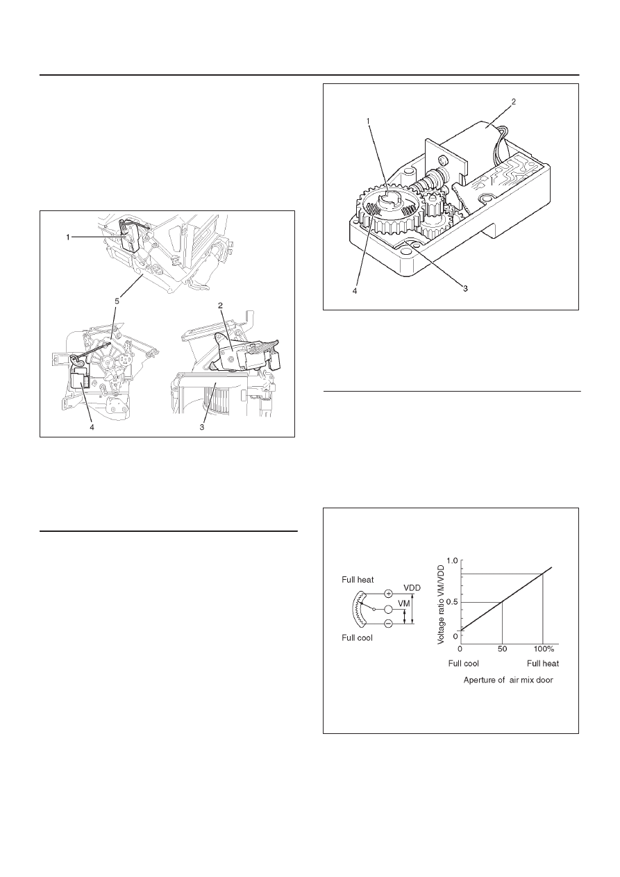
The actuator changes the motor speed using the gear
and drives each door rotating the output axis united with
the sliding contact.

860RW026

Legend

(1) Output Axis
(2) Motor
(3) Printed Circuit Board
(4) Sliding Contact

The mode and mix actuators are common actuators with
the built-in potentiometer.  For the intake actuator, the
contact switch type is selected.
The potentiometer is a register assembled to the printed
circuit board of the mix and mode actuators.  It detects the
air mix door position specified by rotation of the output
axis as a ratio of the variable terminal (VM) voltage
against the reference voltage (VDD: 5V), then signals the
value to the automatic air conditioner control unit.

C01RX016

1A–80 HEATING, VENTILATION AND AIR CONDITIONING (HVAC)

Movement of Mix Actuator

Position of the air mix door is determined by the controller
on the automatic air conditioner control unit.
As the heat or cool side of the controller is grounded, the
transistor on the driver is activated and, thus, the motor
rotation is turned on.  The sliding contact connected to the
motor sends the position detection signal from the
potentiometer to the automatic air conditioner control
unit.  As the set temperature and interior temperature are
balanced, the controller returns to the neutral and the
motor rotation is stopped.

C-43

Rotation

direction

Remarks

(+) side

(-) side

direction

8

6

Clockwise

Full heat side

6

8

Counter

clockwise

Full cool side

C01RX005

Movement of Mode Actuator

As target position of the mode door is decided on the
controller of the control unit, the control unit reads the
position detection signal from the actuator to select the
clockwise or counter clockwise motor rotation direction.
Grounding the controller VENT or DEF side after the
direction selection activates the transistor on the driver,
thus turning on the motor rotation.  Accompanying the
motor rotation, the sliding contact rotates, too.  When the
target position is reached, the controller on the control
unit returns to the neutral and the motor stops.

Conduction pin

Rotation

direction

Remarks

(+) side

(-) side

direction

5

1

Clockwise

VENT to DEF

direction

1

5

Counter

clockwise

DEF to VENT

direction

C01RX017

HEATING, VENTILATION AND AIR CONDITIONING (HVAC) 1A–81

Movement of Intake Actuator

The controller on the automatic heater/air conditioner
control unit selects an intake mode to be used.
As the Terminal No.5 C-33 is grounded via the sliding
contact on the terminal plate, the transistor on the driver is
activated, thus turning on the motor rotation.  Then,
accompanying move of the motor, the sliding contact
rotates until grounding of the Terminal No.5 C-33 is
removed, thus stopping the motor.

Grounding

terminal

Rotation

direction

Remarks

No.5 C-33

Clockwise

RE-CIRCULATI

ON

MIX

FRESH

C01RX006

Overview of Automatic Control of
Automatic Air Conditioner

The automatic air conditioner on this vehicle has the
following features:


Interior temperature control.


Air flow control.


Mode (blow port) control.


Intake (switching between fresh air and interior air)
control.


Heater start timing control.


Cooler start timing control.


Evaporator anti-freeze control.

1A–82 HEATING, VENTILATION AND AIR CONDITIONING (HVAC)

Automatic Air Conditioning System

System Overview (Chart)

Conditions both inside and outside the vehicle are
detected by sensors (in-car temperature sensor, ambient
temperature sensor, duct sensor, sun sensor, speed
sensor, and water temperature sensor). These sensors
send signals to the control unit.
Potentiometer position sensors send data to the control
unit. Signals related to control panel settings are also sent
to the control unit.

In response to the signals received, the control unit
automatically adjusts air-mix door aperture (outlet air
temperature), fan speed (forced air volume), and air
intake (outside air, recirculated inside air, or a mixture of
the two).

F01R200003


Content   ..  25  26  27  28   ..