Isuzu Amigo / Axiom / Trooper / Rodeo / VehiCross. Manual - part 16


  Index      Isuzu     Isuzu Amigo / Axiom / Trooper / Rodeo / VehiCross - service repair manual 1999-2002 year


Search            


Content   ..  14  15  16  17   ..


Isuzu Amigo / Axiom / Trooper / Rodeo / VehiCross. Manual - part 16


HEATING, VENTILATION AND AIR CONDITIONING (HVAC) 1A–35

Refrigerant Recycling

Recycle the refrigerant recovered by J-39500
(ACR

4

:HFC-134a Refrigerant Recovery / Recycling /

Recharging / System) or equivalent.
For the details of the actual operation, follow the steps in
the ACR

4

(or equivalent) Manufacturer’s Instructions.

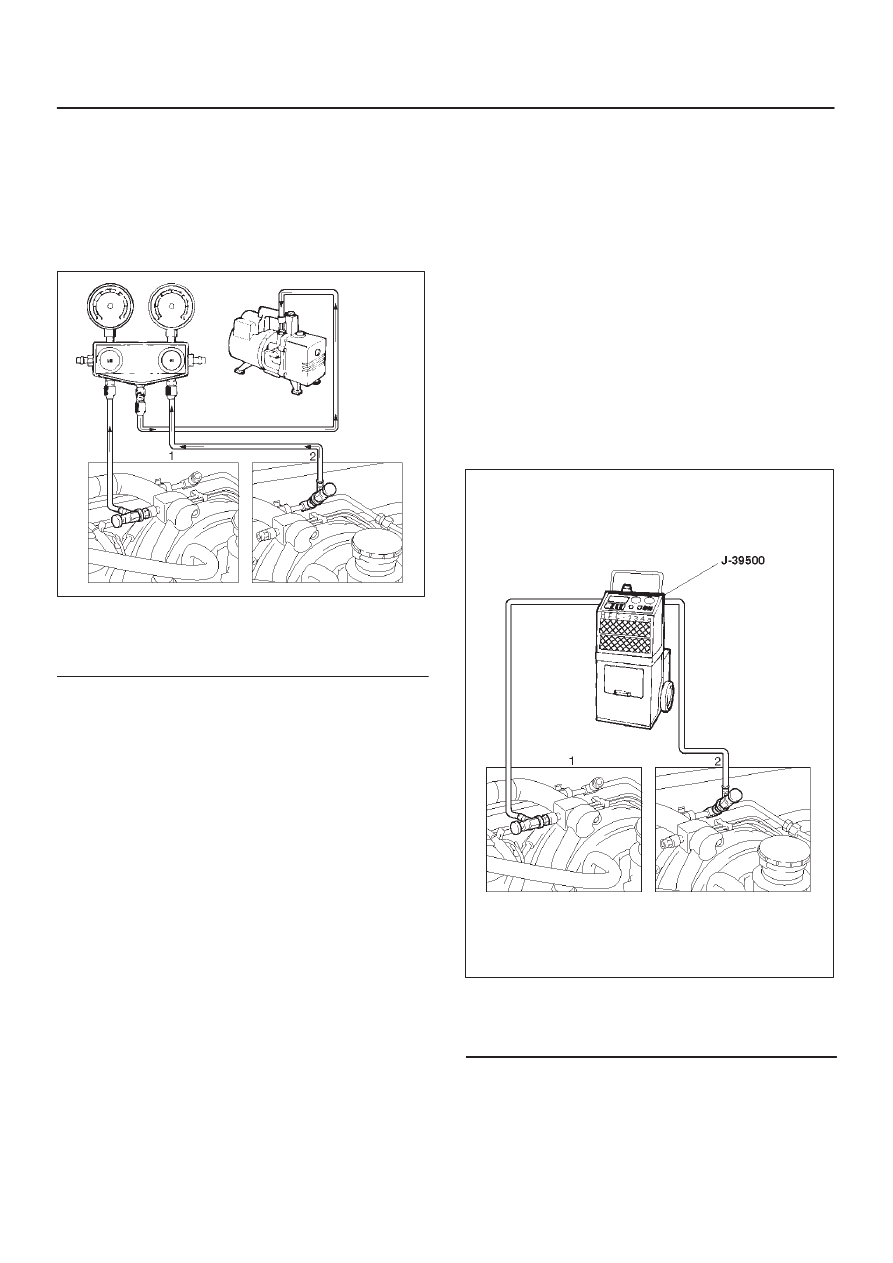
Evacuation of The Refrigerant System

901R100023

Legend

(1) Low Side
(2) High Side

NOTE: Explained below is a method using a vacuum
pump. Refer to the ACR

4

(or equivalent) manufacturer’s

instructions when evacuating the system with a ACR

4

(or

equivalent).

Air and moisture in the refrigerant will cause problems in
the air conditioning system. Therefore, before charging
the refrigerant, be sure to evacuate air and moisture thor-
oughly from the system.

1. Connect the gauge manifold.

D

High-pressure valve (HI) — Discharge-side.

D

Low-pressure valve (LOW) — Suction-side.

2. Discharge and recover the refrigerant.
3. Connect the center hose of the gauge manifold set to

the vacuum pump inlet.

4. Operate the vacuum pump, open shutoff valve and

then open both hand valves.

5. When the low-pressure gauge indicates

approximately 750 mmHg (30 inHg), continue the
evacuation for 5 minutes or more.

6. Close both hand valves and stop the vacuum pump.
7. Check to ensure that the pressure does not change

after 10 minutes or more.

D

If the pressure changes, check the system for
leaks.

D

If leaks occur, retighten the refrigerant line
connections and repeat the evacuation steps.

8. If no leaks are found, again operate the vacuum pump

for 20 minutes or more.  After confirming that the
gauge manifold pressure is at 750 mmHg (30 inHg),
close both hand valves.

9. Close positive shutoff valve. Stop the vacuum pump

and disconnect the center hose from the vacuum
pump.

Charging The Refrigerant System

There are various methods of charging refrigerant into the
air conditioning system.
These include using J-39500 (ACR

4

:HFC-134a

Refrigerant Recovery/Recycling/Recharging/System) or
equivalent and direct charging with a weight scale
charging station.

Charging Procedure

D

ACR

4

(or equivalent) Method

For the charging of refrigerant recovered by ACR

4

(or

equivalent), follow the manufacturer’s instruction.

901R100022

Legend

(1) Low Side
(2) High Side

D

Direct charging with a weight scale charging
station method

1. Make sure the evacuation process is correctly

completed.

2. Connect the center hose of the manifold gauge to the

weight scale.

1A–36 HEATING, VENTILATION AND AIR CONDITIONING (HVAC)

3. Connect the low pressure charging hose of the

manifold gauge to the low pressure side service valve
of the vehicle.

4. Connect the high pressure charging hose of the

manifold gauge to the high pressure side service
valve of the vehicle.

901R100021

Legend

(1) Low Side
(2) High Side
(3) Refrigerant Container
(4) Weight Scale

5. Place the refrigerant container(3) up right on a weight

scale(4).
Note the total weight before charging the refrigerant.

a. Open the refrigerant container valve.
b. Open the low side vale on the manifold gauge set.

Refer to the manufacturer’s instructions for a
weight scale charging station.

901RS144

6. Perform a system leak test:

D

Charge the system with approximately 200 g
(0.44 lbs) of HFC-134a.

D

Make sure the high pressure valve of the manifold
gauge is closed.

D

Check to ensure that the degree of pressure does
not change.

D

Check for refrigerant leaks by using a HFC-134a
leak detector.

D

If a leak occurs, recover the refrigerant. Repair the
leak and start all over again from the first step of
evacuation.

7. If no leaks are found, continue charging refrigerant to

the air conditioning system.

D

Charge the refrigerant until the scale reading
decreases by the amount of the charge specified.

Specified amount: 700 g (1.54 lbs)

D

If charging the system becomes difficult:

1. Run the engine at idle and close all the vehicle

doors.

2. Turn A/C switch “ON”.
3. Set the fan switch to its highest position.
4. Set the air source selector lever to “CIRC”.
5. Slowly open the low side valve on the manifold

gauge set.

WARNING: BE ABSOLUTELY SURE NOT TO OPEN
THE HIGH PRESSURE VALVE OF THE MANIFOLD
GAUGE. SHOULD THE HIGH PRESSURE VALVE BE
OPENED, THE HIGH PRESSURE REFRIGERANT
WOULD FLOW BACKWARD, AND THIS MAY CAUSE
THE REFRIGERANT CONTAINER TO BURST.

HEATING, VENTILATION AND AIR CONDITIONING (HVAC) 1A–37

8. When finished with the refrigerant charging, close the

low pressure valve of the manifold gauge and
container valve.

9. Check for refrigerant leaks.

Checking The A/C System

1. Run the engine and close all the vehicle doors.
2. Turn A/C switch “ON”, set the fan switch to its highest

position.

3. Set the air source switch to “CIRC”, set the

temperature switch to the full cool position.

4. Check the high and low pressure of the manifold

gauge.

D

Immediately after charging refrigerant, both high
and low pressures might be slightly high, but they
settle down to the pressure guidelines shown
below:

D

The ambient temperature should be between
25–30

°

C (77–86

°

F).

D

The pressure guideline for the high-pressure side is
approximately 1372.9–1863.3 kPa (199.1–270.2
psi).

D

The pressure guideline for the low-pressure side is
approximately 147.1–294.2 kPa (21.3–42.7  psi).

D

If an abnormal pressure is found, refer to 

Checking

The Refrigerant System With Manifold Gauge in
this section.

5. Put your hand in front of the air outlet and move the

temperature switch of the control panel to different
positions.  Check if the outlet temperature changes as
selected by the control switch.

1A–38 HEATING, VENTILATION AND AIR CONDITIONING (HVAC)

Compressor Assembly

Compressor Assembly and Associated Parts (6VE1)

852R100002

Legend

(1) Compressor Bracket
(2) Magnetic Clutch Harness Connector
(3) Compressor
(4) O-ring

(5) To Evaporator
(6) Suction Line (Low-Pressure Hose)
(7) Discharge Line (High-Pressure Hose)
(8) To Condenser
(9) Serpentine Belt

Removal

1. Disconnect the battery ground cable.
2. Discharge and recover refrigerant

D

Refer to 

Refrigerant Recovery in this section.

3. Disconnect magnetic clutch harness connector.


Content   ..  14  15  16  17   ..