Isuzu engine C22NE / 22LE / 20LE. Manual - part 84


  Index      Isuzu     Isuzu engine C22NE / 22LE / 20LE - service manual


Search            


Content   ..  82  83  84  85   ..


Isuzu engine C22NE / 22LE / 20LE. Manual - part 84


DRIVEABILITY AND EMISSIONS  6E1-165

DIAGNOSTIC TROUBLE CODE (DTC) (Flash DTC = 18)

DIGITALLY CONTROLED SIGNAL TO NOISE ENHANCEMENT FILTER FAILURE

Circuit Description

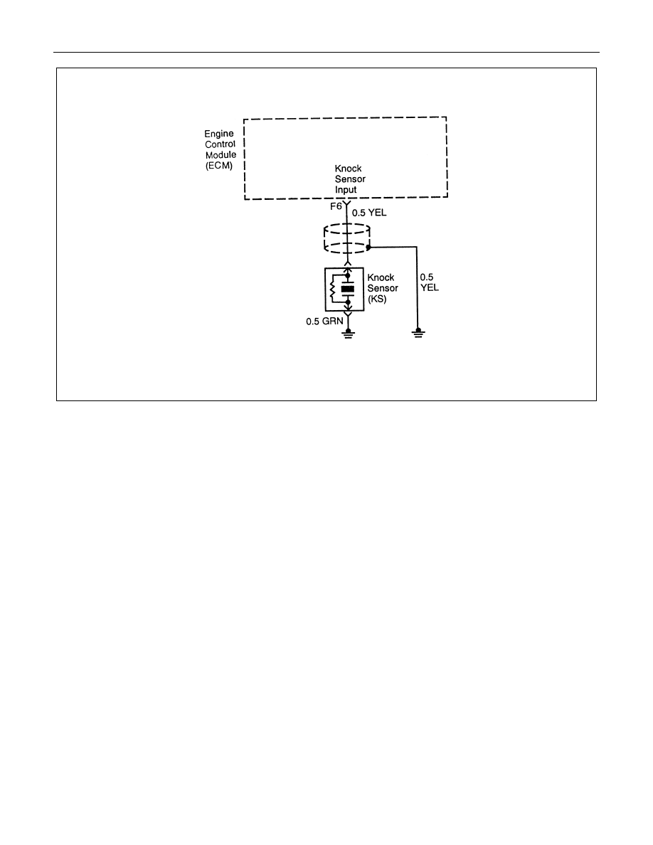
The knock sensor (KS) system is used to detect

engine detonation. The knock sensor produced an AC

voltage signal. The knock sensor sends this signal to

the ECM. The amplitude and the frequency of the AC

voltage signal depends upon the knock level being

detected. The ECM will then retard the spark timing

based on the signals from the Knock Sensor.

This code detects a digitally controlled signal to noise

enhancement filter failure. Then the DTC 18 will set.

Conditions for Setting the DTC

• ECM powered up, Engine running, Electronic spark

control enabled and Engine rpm is greater than 96

rpm.

• Malfunction 16 is not triggered.

Action Taken When the DTC Sets

• The Malfunction Indicator Lamp (MIL) will illuminate

the second time the fault is detected.

• The ECM will use a calculated spark retard value in

order to minimize the knock during the conditions

when the knock is likely to occur. The calculated

value will vary based on the engine speed and load.

Conditions for Clearing the MIL/DTC

Once the ECM determines that a fault(s) has been

rectified then the CEL will switch OFF, although the

fault code will remain in the ECM memory.

Any fault codes will remain in ECM memory until -

1. They are cleared by disconnecting the Battery for

more than 30 seconds.

2. A service tool such as Tech 2 is used to clear them.

3. Ten consecutive starts without logging a fault.

Diagnostic Aids

Correct any abnormal engine noise before using the

diagnostic table.

Check for an open ignition feed circuit.

Test Description

Number(s) below refer to the step number(s) on the

Diagnostic Table.

2. If the conditions for the test as described above are

met, a Diagnostic Trouble Code 18 will set and MIL

will illuminate.

6E1-166  DRIVEABILITY AND EMISSIONS

5. Any circuitry, that is suspected as causing the

complaint, should be thoroughly checked for

backed out terminals, improper mating, broken

locks, improperly formed or damaged terminals,

poor terminal to wiring connections or physical

damage to the wiring harness.

9. If the KS module was previously replaced and the

Diagnostic Trouble Code resets, a malfunctioning

ECM is indicated.

DTC (Flash DTC = 18)

Digitally Controlled Signal To Noise Enhancement Filter Failure

Step

Action

Value(s)

Yes

No

1

Was the On-Board Diagnostic(OBD) System Check

performed?

-

Go to Step2

Go to

Powertrain

OBD System

Check

2

1.  Operate the engine within the conditions specified in

the diagnostic support Conditions for Setting the

Diagnostic Trouble Code.

2.  Using a Scan Tool, monitor the Specific DTC

information for DTC 18.

3.  Observe the test results.

Does the Scan Tool indicate the DTC 18.

-

Go to Step 3

Go to

Diagnostic

Aids

3

1.  Turn ON the ignition with the engine leaving OFF.

2.  Disconnect the KS electrical connector.

3.  Using a Digital Voltmeter (DVM), measure the voltage

between the KS signal circuit at the knock sensor

harness connectors and ground.

Is the voltage at the specified value?

Approx.5.0V

Go to Step 4

Go to Step 7

4

Measure the resistance of the KS sensor by connecting

the between the KS sensor terminal and the engine block.

Is the resistance of the KS sensor near the specified

value?

100K OHMS

Go to Step 5

Go to Step 8

5

1.  Check the KS signal circuit for a poor terminal

connection at the knock sensor.

2. If a problem is found, repair as necessary. Refer to

Wiring Repairs in Engine Electrical.

Was a problem found?

-

Go to Step 6

Go to Step 8

DRIVEABILITY AND EMISSIONS  6E1-167

DTC (Flash DTC = 18)

Digitally Controlled Signal To Noise Enhancement Filter Failure (Cont’d)

Step

Action

Value(s)

Yes

No

6

1.  Re-Connect the KS Sensor in order to monitor the

voltage between the KS sensor terminal and the engine

ground.

2.  Tap on the engine lift bracket, near the KS Sensor,

while observing the signal indicated on the Scan Tool.

Is any signal indicated on the while tapping on the engine

lift bracket?

-

Go to Step 10

Go to Step 7

7

1.  Turn OFF the ignition.

2.  Disconnect the ECM.

3.  Turn ON the ignition.

4.  Check the KS signal circuit between the ECM and the

KS sensor connector for an open, a short to voltage, or

a short to ground.

5.  If a wiring problem is found, repair as necessary.

Was a problem found?

-

Go to Step 10

Go to Step 9

8

Replace the KS Sensor. Refer to Knock Sensor.

Is action complete?

-

Go to Step 10

-

9

Replace the EPROM or ECM. 

Note) Refer to 6E1-243.

Is the action complete?

-

Go to Step 10

-

10

1.  Using the Scan Tool, select the DTC and the Clear

Info.

2.  Start the Engine.

3.  Idle at the normal operating temperature.

4.  Select Specific DTC.

5.  Enter the DTC number which was set.

6.  Operate the vehicle within the conditions for setting this

DTC as specified in the supporting text.

Does the Scan Tool indicate that this diagnostic ran and

passed?

-

Go to Step 11

Go to Step 2

11

Using the Scan Tool, select the Capture Info and the

Review Info.

Are any DTC displayed that have not been diagnosed?

-

Go to the

applicable

Diagnostic

Trouble Code

table

System OK

6E1-168  DRIVEABILITY AND EMISSIONS


Content   ..  82  83  84  85   ..