Isuzu Trooper (1998-2002 year). Manual - part 620


  Index      Isuzu     Isuzu Trooper - service repair manual 1998-2002 year


Search            


Content   ..  618  619  620  621   ..


Isuzu Trooper (1998-2002 year). Manual - part 620


6E–128

4JX1–TC ENGINE DRIVEABILITY AND EMISSIONS

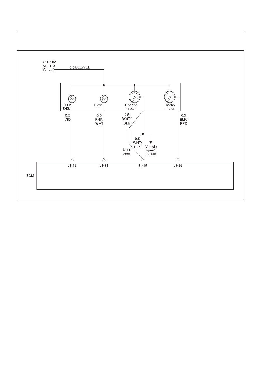
Diagnostic Trouble Code (DTC) P0381 (Flash DTC 67)

 Glow Lamp Circuit Open/Short

060RW136

Circuit Description

Glow Lamp Circuit receives current through Meter 10A
fuse, Glow lamp being circuited to ECM.

Action Taken When the DTC Sets

D

The ECM will store conditions which were present
when the DTC was set as Freeze Frame and in the
Failure Records data.

Conditions for Clearing the MIL/DTC

D

DTC P0381 can be cleared by using the Tech 2 “Clear
Info” function or by disconnecting the ECM battery
feed.

Diagnostic Aids

An intermittent may be caused by a poor connection,
rubbed-through wire insulation or a wire broken inside the
insulation.  Check for:

D

Poor connection – Inspect the ECM harness and
connectors for improper mating, broken locks,
improperly formed or damaged terminals, and poor
terminal-to-wire connection.

D

Damaged harness – Inspect the wiring harness for
damage.

6E–129

4JX1–TC ENGINE DRIVEABILITY AND EMISSIONS

DTC P0381 – Glow Lamp Circuit Open/Short


Step

Action

Value(s)

Yes

No

1

Was the “On-Board Diagnostic (OBD) System Check”
performed?

Go to 

Step 2

Go to 

OBD

System

Check

2

1. Review and record Failure Records information.
2. Clear DTC P0381.
3. Observe DTCs.

Is DTC P0381 set?

Go to 

Step 3

Refer to

Diagnostic

Aid

3

1. Ignition “OFF.”
2. Remove the Meter assembly.
3. Check for an open or a short to ground in the Glow

Lamp circuit. 

4. If a problem is found, repair as necessary. 
(On electric bulb of the Glow Lamp, The Glow Lamp
harness circuit)

Was a problem found?

Refer to the

Meter in

Electric

section 8

Go to 

Step 4

4

Check the connections at the ECM and replace the
terminals if necessary.

Did any terminals require replacement?

Verify repair 

Go to 

Step 5

5

Replace the ECM (Refer to the Data Programming in
Case of ECM change).

Is the action complete?

Verify repair

6E–130

4JX1–TC ENGINE DRIVEABILITY AND EMISSIONS

Diagnostic Trouble Code (DTC) P1403 (Flash DTC 32)

 EGR EVRV Fault

060RW135

Circuit Description

EGR EVRV Circuit has a common power source in
parallel with EGR, VSV, RPCV, and Intake Throttle Motor.
This may cause multiple DTCs. On such occasion, refer
to “Multiple ECM Information sensor DTCs Set”.

Diagnostic Aids

Check for the following conditions:

D

Poor connection or damaged EVRV – Inspect the
wiring harness for damage.

D

Ensure EVRV is correctly mounted.  See 

On-Vehicle

Service.

Reviewing the Failure Records vehicle mileage since the
diagnostic test last failed may help determine how often
the condition that caused the DTC to be set occurs.  This
may assist in diagnosing the condition.

Test Description

Number(s) below refer to the step number(s) on the
Diagnostic Chart
3. A malfunctioning MAP sensor can set an EGR DTC.

The MAP sensor could send a constant signal which
is not low enough to set a low MAP DTC.  The
constant signal from the MAP sensor also may not
be high enough to set a high MAP DTC. This step
verifies that the MAP sensor is responding.

6E–131

4JX1–TC ENGINE DRIVEABILITY AND EMISSIONS

DTC P1403 – EGR EVRV Fault


Step

Action

Value(s)

Yes

No

1

Was the “On-Board Diagnostic (OBD) System Check”
performed?

Go to 

Step 2

Go to 

OBD

System

Check

2

Check the EVRV circuit.

Was the EVRV circuit darmage?

Replace the

EVRV circuit

Go to 

Step 3

3

1. Start the engine.
2. Monitor the MAP signal with a scan tool while idling.
3. While idling, jab the accelerator pedal about halfway

down and immediately let the engine return to idle.

Did the MAP value on the scan tool show an immediate
large change?

Go to 

Step 5

Go to 

Step 4

4

Replace the MAP sensor.

Is the action complete?

Verify repair

5

1. Inspect the exhaust system for modification of

original installed parts or leaks.

2. If a problem was found, repair exhaust system as

necessary.

Was a condition present that required repair?

Go to 

Step 8

Go to 

Step 6

6

1. Remove the EGR valve.
2. Visually and physically inspect the pintle, valve

passages and the adapter for excessive deposits or
any kind of a restriction.

3. If a problem is found, clean or replace EGR system

components as necessary.

Was a condition present that required repair?

Go to 

Step 8

Go to 

Step 7

7

1. Inspect the EGR passages for a blockage caused

by excessive deposits or other damage.

2. If a problem is found, correct the condition as

necessary.

Was a condition present that required repair?

Go to 

Step 8

Refer to

Diagnostic

Aids

8

1. Review and record the scan tool Failure Records

data.

2. Clear DTC and monitor the scan tool System Info

Screen while operating the vehicle as specified in
“Diagnostic Aids.”

3. Using a scan tool, monitor “DTC” info for DTC

P1403 until the DTC P1403 test runs.

4. Note the test result.

Does the scan tool indicate DTC P1403 failed this
ignition?

Go to the last

step

completed in

this

diagnostic

chart 

Repair

complete


Content   ..  618  619  620  621   ..