Isuzu Trooper (1998-2002 year). Manual - part 585


  Index      Isuzu     Isuzu Trooper - service repair manual 1998-2002 year


Search            


Content   ..  583  584  585  586   ..


Isuzu Trooper (1998-2002 year). Manual - part 585


6D – 14 ENGINE ELECTRICAL
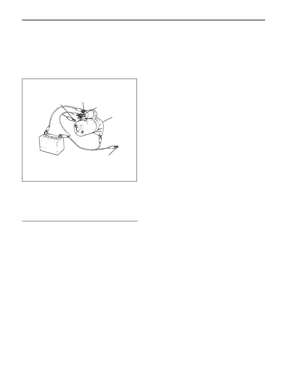
MAGNETIC SWITCH

Pull-out test

Connect the magnetic switch to the battery as shown.
The negative side to the “M” terminal and the magnetic
switch body (housing); the positive side to the “S”
terminal. If the pinion has been ejected, the pull-in coil
is satisfactory.

Legend

(1) Terminal “S”
(2) Terminal “M”
(3) Starter
(4) For Return Test
(5) For Hold-In Test

Hold-in test

1. Next disconnect the “M” terminal.
2. The pinion should remain in the ejected position.

Return test

When the switch body is disconnected, the pinion
should return quickly.

2

1

5

3

4

065RW055

ENGINE ELECTRICAL 6D – 15

CHARGING SYSTEM

GENERAL DESCRIPTION

GENERATOR

CHARGING CIRCUIT

The charging system is the IC integral regulator
charging system and its main components are
connected as shown in Figure.
The regulator is a solid state type and it is mounted
along with the brush holder assembly inside the
generator installed on the rear end cover.

The generator does not require particular maintenance
such as voltage adjustment. The rectifier connected to
the stator coil has nine diodes to transform A.C. voltage
into D.C. voltage. This D.C. voltage is connected to the
output terminal of generator.

A06RW001

Condenser

Generator

Stator Coil

IC Regulator

Starter
SW

Rotor Coil

Battery

P

F

E

B S

L

Relay

B

S

L

QOS

065R200028

6D – 16 ENGINE ELECTRICAL

DIAGNOSIS

GENERAL ON-VEHICLE INSPECTION

The operating condition of the charging system is
indicated by the charge warning lamp. The warning
lamp comes on when the starter swtich is turned to
“ON” position. The charging system operates normally

if the lamp goes off when the engine starts. If the
warning lamp shows abnormality or if undercharged or
overcharged battery condition is suspected, perform
diagnosis by checking the charging system as follows:

Condenser

Generator

Stator Coil

IC Regulator

Starter
SW

Rotor Coil

Battery

P

F

E

B S

L

Relay

B

S

L

QOS

065R200028

1. Check visually the belt and wiring connector.
2. With the engine in stop status, turn the starter

switch to “ON” position and observe the warning
lamp.
1) If lamp does not come on:

Disconnect wiring connector from generator,
and ground terminal “L” on connector side.

2) If lamp comes on:

Repair or replace the generator.

ENGINE ELECTRICAL 6D – 17

UNIT REPAIR

5

4

3

2

1

7

6

10

9

8

11

12

066RW022

Legend

(1)

Pulley Nut

(2)

Pulley

(3)

Front Cover Assembly

(4)

Rotor Assembly

(5)

Stator Assembly

(6)

Through Bolt

(7)

Nut

(8)

Terminal Insulator Plate

(9)

Rear Cover Assembly

(10)

Diode

(11)

Brush Holder

(12)

Regulator Assembly


Content   ..  583  584  585  586   ..