Isuzu Trooper (1998-2002 year). Manual - part 551


  Index      Isuzu     Isuzu Trooper - service repair manual 1998-2002 year


Search            


Content   ..  549  550  551  552   ..


Isuzu Trooper (1998-2002 year). Manual - part 551


6A – 12 ENGINE MECHANICAL

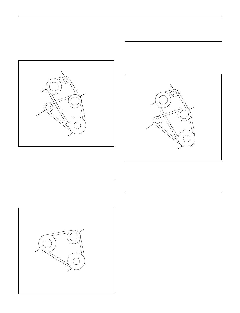
Drive Belt Adjustment

Check the drive belt tension
Depress the drive belt mid-portion with a 98 N (10 kg/
22 lb) force.

Drive Belt Deflection: 10 mm (0.39 in)

Check the drive belt for cracking and other damage.

Legend

(1) Crankshaft pulley
(2) Generator pulley
(3) Cooling fan pulley
(4) A/C compressor pulley
(5) Belt tensioner pulley

Cooling Fan Pulley Drive Belt

Fan belt tension is adjusted by moving the generator.
Depress the drive belt mid-portion with a 98 N (10 kg/ 
22 lb) force.

Legend

(1) Crankshaft pulley
(2) Generator pulley
(3) Cooling fan pulley

Compressor Pulley Drive Belt

Move the tensioner pulley as required to adjust the
compressor drive belt tension.
Depress the drive belt mid-portion with a 98 N (10 kg/
22 lb) force.

Legend

(1) Crankshaft pulley
(2) Generator pulley
(3) Cooling fan pulley
(4) A/C compressor pulley
(5) Belt tensioner pulley

5

3

2

4

1

012RW110

3

2

1

012RW084

5

3

2

4

1

012RW110

ENGINE MECHANICAL 6A – 13

VALVE CLEARANCE ADJUSTMENT

1. Install 2.80 mm valve adjuster (shim) first when

reassembling the engine.
Thickness mark faces down.

2. Measure the valve clearance after installing cam

carrier assy with camshafts.

3. Change the adjuster using a special tool when the

clearance is out of tolerance.
Valve Clearance Adjusting Tool: 5-8840-2590-0

VALVE CLEARANCE (When cold condition)

Inlet

0.15 ± 0.05 mm

Exh

0.25 ± 0.05 mm

COMPRESSION PRESSURE
MEASUREMENT

1. Start the engine and allow it to idle until the coolant

temperature reaches 70 – 80°C (158 – 176°F).

2. Remove the following parts.

Glow plugs

Fuel cut solenoid connector

QOS (Quick-On Start System) fuse in the fuse
box.

3. Set the adapter and compression gauge to the No.

1 cylinder glow plug hole.
Compression Gauge 
(with Adapter): 5-8840-2008-0 

4. Turn the engine over with the starter motor and take

the compression gauge reading.

Compression Pressure at 200 rpm

Standard: 3040 kPa (31 kg/cm

2

/441 psi)

Limit: 2160 kPa (22 kg/cm

2

/313 psi)

5. Repeat the procedure (Steps 3 and 4) for the

remaining cylinders.

QUICK-ON START 4 SYSTEM

Quick-On Start System Inspection Procedure

1. Disconnect the ECT-sensor connection around the

thermostat outlet pipe.

2. Turn the starter switch to the “ON” position.

If the Quick-On Start 4 System is operating
properly, the glow relay will make a clicking sound
within seven seconds after the starter switch is
turned on.

3. Measure the glow plug terminal voltage with a

circuit tester immediately after turning the starter
switch to the “ON” position.

Glow Plug Terminal Voltage: approx. 12V

NOTE: Electrical power to the quick-on start system will
be cut after the starter has remained in the “ON”
position for twenty seconds.
Turn the starter switch to the “OFF” position and back
to the “ON” position.
This will reset the Quick-On Start 4 System.

014RW150

6A – 14 ENGINE MECHANICAL

TIGHTENING TORQUE

Timing Gear Case, Timing Gear

N·m (kg·m/lb·ft)

75(7.6/55)

Apply engine oil to
thread and seat

8(0.8/69lb•in)

20(2.0/14)

51(5.2/38)

25(2.5/18)

020R200001

ENGINE MECHANICAL 6A – 15

Cylinder Head, Flywheel, Crank Case, Oil Pan

N·m (kg·m/lb·ft)

012R200008

1st

49N•m(5.0kg•m/36 Ib ft)

167(17.0/123)

8(0.8/69lb•in)

20(2.0/14)

20(2.0/14)

30(3.1/22)

24(2.4/17)

2nd

60

°

1st

59N•m(6.0kg•m/43 Ib ft)

Apply engine oil to thread

Apply engine oil to thread

Apply engine oil to thread

2nd

60

°

-90

°

3rd

60

°

-90

°

1st

29N•m(3.0kg•m/22 Ib ft)

2nd

45

°

-60

°

3rd

60

°

22(2.2/16)


Content   ..  549  550  551  552   ..