Isuzu Trooper (2000 year). Manual - part 438


  Index      Isuzu     Isuzu Trooper - service repair manual 2000 year


Search            


Content   ..  436  437  438  439   ..


Isuzu Trooper (2000 year). Manual - part 438


7C–16

CLUTCH

Installation

1. Install damper cylinder assembly.
2. Install master cylinder assembly.
3. Install slave cylinder assembly and heat protector.
4. Install oil line pipe.
5. Install pedal assembly and switch.
6. Install pin and jaw joint pin.

Adjustment

Clutch Pedal Adjustment

1. With clutch switch

1. Disconnect clutch switch (2) connector.

2. Loosen lock nut, then turn switch out until there is

a gap between the switch plunger and clutch
pedal. 

203RW003

Legend

(1) Push Rod
(2) Clutch Switch

2. Loosen clutch master cylinder push rod lock nut. Turn

push rod by hand to set clutch pedal height (5) to
within specification.

Clutch pedal height (5): 217 mm – 227 mm
(8.543 in – 8.937 in) 

203RW004

Legend

(3) Floor Panel
(4) Pedal Free Play
(5) Clutch Pedal Height

3. Tighten push rod lock nut. 
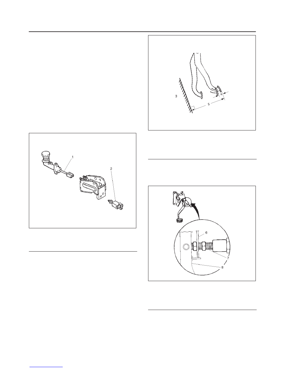
4. With clutch switch

1. Turn the clutch switch until the switch bolt just

touches the clutch pedal arm.

203RW005

Legend

(6) Blacket
(7) Clutch Switch Bolt
(8) Clutch Pedal Arm

CLUTCH

7C–17

2. Adjust clutch switch by backing it out half a turn,

and measure the clearance (E) between the
clutch pedal arm and the clutch switch.

203RW006

Legend

(9) Back out Switch 1/2 turn

(10) Bracket

(11) Clutch Switch Bolt

(12) Lock Nut
(13) Clutch Pedal Arm

3. Lock the lock nut.

4. Connect clutch switch connector. 

Clutch Switch and Clutch Pedal Clearance (E) 

0.5 mm – 1.5 mm (0.020 in – 0.059 in)

5. After adjusting the clutch pedal height, push the

clutch pedal by hand rightly to check the clutch pedal
free play (4) to within specification. 

Pedal Free Play (4)

5 mm – 15 mm (0.20 in – 0.59 in)

203RW004

6. Clutch pedal engagement height inspection:

1. Operate the parking brake lever and block the

wheels.

2. Start the engine, fully step on the clutch pedal,

and move the shift lever to 1st position.

3. With the engine idling, release the clutch pedal

slowly and measure its stroke  just prior to its
clutching position.

Clutch Pedal Engagement Height (14)

MIN. 30 mm (1.18 in)

7. If the measured value exceeds the specified limit,

check the following points. Repair if necessary:

D

Hydraulic circuit for fluid leakage or air in circuit.

D

Clutch disc warped.

D

Diaphragm spring weakened or tip of fingers worn.

D

Driven plate sticking on sprines.

D

Release bearing worn or damaged.

D

Master cylinder and slave cylinder worn.

203RW007

Legend

(3) Floor Panel

(14) Clutch Pedal Engagement Height

7C–18

CLUTCH

Torque Specifications

D

Master cylinder to dash panel
Torque: 16 N·m (12 lb ft)

D

Clutch pedal to dash panel
Torque: 21 N·m (15 lb ft)

D

Master cylinder push rod to yoke
Torque: 17 N·m (12 lb ft)

D

Clutch pipe to master cylinder
Torque: 12 N·m (9 lb ft)

D

Clutch pipe to flexible hose
Torque: 16 N·m (12 lb ft) 

D

Slave cylinder to case
Torque: 43 N·m (32 lb ft)

D

Slave cylinder bleeder screw
Torque: 8 N·m(69 lb in) 

D

Flexible hose to slave cylinder
Torque: 20 N·m (14 lb ft) 

Bleeding

1. Check the level of clutch fluid in the reservoir and

replenish if necessary

2. Bleeding the slave cylinder.

1. Remove the rubber cap from the bleeder screw

and wipe clean the bleeder screw. Connect a vinyl
tube to the bleeder screw and insert the other end
of the vinyl tube into a transparent container.

2. Pump the clutch pedal repeatedly and hold it

depressed.

203RS005

3. Loosen the bleeder screw to release clutch fluid

with air bubbles into the container, then tighten
the bleeder screw immediately.

4. Release the clutch pedal carefully.  Repeat the

above operation until air bubbles disappear from
the clutch fluid being pumped out into the
container.  During the bleeding operation, keep
the clutch fluid reservoir filled to the specified
level. Reinstall the rubber cap. 

206RW003

Legend

(1) Slave Cylinder
(2) Bleeder Screw
(3) Vinyl Tube

CLUTCH

7C–19

Master Cylinder

208RW017

Inspection and Repair

Inspect the removed parts. If there are abnormalities
such as wear, oil leak or other damage, replace the
master cylinder assembly.

NOTE: The master cylinder assembly cannot be
disassembled because of point–staked rod stopper.


Content   ..  436  437  438  439   ..