Isuzu Trooper (2000 year). Manual - part 63


  Index      Isuzu     Isuzu Trooper - service repair manual 2000 year


Search            


Content   ..  61  62  63  64   ..


Isuzu Trooper (2000 year). Manual - part 63


3C 17

FRONT SUSPENSION

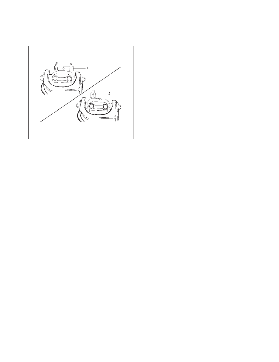
7. Install the camber shims(1) between the chassis

frame and fulcrum pin.

450RS014

8. Install nut assembly.
9. Install bolt and plate, then tighten the bolt to the

specified torque.

Torque: 152 N·m (112 lb ft)

10. Install upper ball joint and tighten it to the specified

torque.

Torque: 57 N·m (42 lb ft)

11. Install nut and cotter pin then tighten the nut to the

specified torque, with just enough additional torque to
align cotter pin holes. Install new cotter pin.

Torque: 98 N·m (72 lb ft)

12. Install speed sensor cable.

3C 18

FRONT SUSPENSION

Lower Control Arm

Lower Control Arm and Associated Parts

450RS015

Legend

(1) Nut and Washer, Front
(2) Bush, Front
(3) Bolt, Front
(4) Nut and Washer, Rear
(5) Bush, Rear
(6) Bolt, Rear
(7) Bolt, Lower Ball Joint

(8) Bolt, Torsion Bar Arm
(9) Torsion Bar Arm Bracket

(10) Torsion Bar

(11) Lower Control Arm

(12) Lower Ball Joint
(13) Shock Absorber
(14) Stabilizer Link

Removal

1. Raise the vehicle and support the frame with suitable

safety stands.

2. Remove wheel and tire assembly. Refer to Wheel

Replacement in this section.

3. Remove the outer track rod from the knuckle. Refer to

Steering Linkage in Steering section.

4. Remove the retaining ring from the front axle driving

shaft to release the shaft from hub. Refer to Front Hub
and Disc in Driveline/Axle section.

5. Support lower control arm with a jack. 
6. Remove front nut and washer.

3C 19

FRONT SUSPENSION

7. Remove rear nut and washer.
8. Remove torsion bar, refer to Torsion Bar

Replacement in this section. 

9. Remove torsion bar arm bracket.

10. Disconnect the stabilizer link at the lower control arm. 

11. Remove the shock absorber lower end from the lower

control arm. 

12. Remove the lower ball joint from the lower control

arm.

13. Remove front bolt.
14. Remove rear bolt.
15. Remove lower control arm.
16. Remove torsion bar arm bolt.
17. Remove lower ball joint bolt.
18. Remove front bushing by using remover J–36833.

901RW034

901RW035

19. Remove rear bushing by using remover J–36834.

901RW051

3C 20

FRONT SUSPENSION

901RW052

Inspection and Repair

Make necessary correction or parts replacement if wear,
damage, corrosion or any other abnormal conditions are
found through inspection.
Check the following parts:

D

Lower control arm

D

Bushing

Installation

1. Install rear bushing by using installer J–36834.

901RW053

2. Install front bushing by using installer J–36833.

901RW036

3. Install lower ball joint bolt.
4. Install torsion bar arm bolt.
5. Install lower control arm.
6. Install rear bolt.
7. Install front bolt.
8. Install lower ball joint and tighten it to the specified

torque.

Torque: 103 N·m (76 lb ft)

9. Install shock absorber and tighten it to the specified

torque.

Torque: 82 N·m (61 lb ft)

10. Install stabilizer link and tighten it to the specified

torque.

Torque: 50 N·m (37 lb ft)

11. Install torsion bar arm bracket and tighten it to the

specified torque.

Torque: 116 N·m (85 lb ft)

12. Install Torsion bar, refer to Torsion Bar Replacement

in this section. 


Content   ..  61  62  63  64   ..