Isuzu Trooper (2000 year). Manual - part 26


  Index      Isuzu     Isuzu Trooper - service repair manual 2000 year


Search            


Content   ..  24  25  26  27   ..


Isuzu Trooper (2000 year). Manual - part 26


HEATING, VENTILATION AND AIR CONDITIONING (HVAC) 1A–73

Installation

1. Place the clutch coil assembly (1) on the front head

with the terminals positioned at the “marked” location.

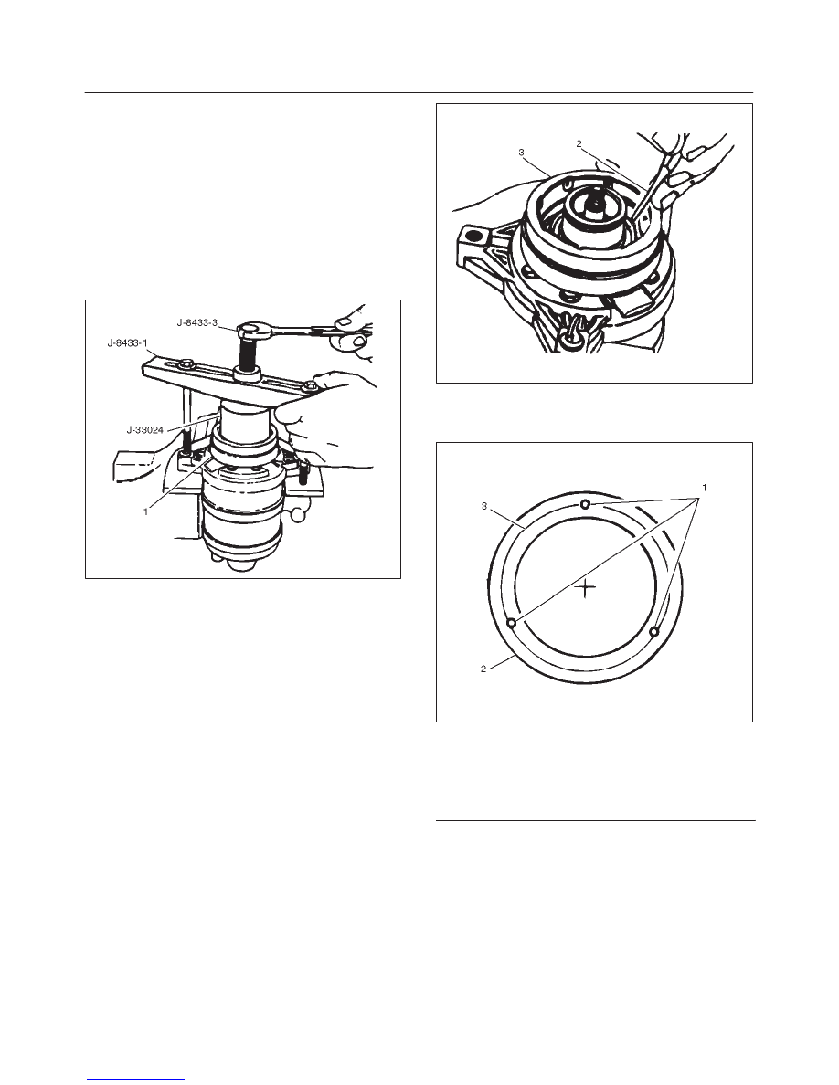
2. Place the J-33024 clutch coil installer over the internal

opening of the clutch coil housing and align installer
with the compressor front head.

3. Center the J-8433-1 puller crossbar in the

counter-sunk center hole of the J-33024 clutch coil
installer. Install the J-33026 through bolts and
washers through the crossbar slots and thread them
into the holding fixture J-33026 to full fixture
thickness.

901RW007

4. Turn the center forcing screw of J-8433-1 puller

crossbar to force the clutch coil onto the front head.
Be sure clutch coil and J-33024 installer stay “in-line”
during installation.

5. When coil is fully seated on the front head, use a 1/8 in

diameter drift punch (2) and stake the front head at
three places 120 degrees apart, to ensure clutch coil
(3) remains in position.

871RW004

D

Stake size should be only one-half the area of the
punch tip and be only approximately 0.28–0.35 mm
(.010–.015 in) deep.

871RW005

Legend

(1) Stake Front Head 0.28–0.35 mm Deep

(0.10–015 in)

(2) Clutch Coil Housing
(3) Front Head Surface

6. Install rotor and bearing assembly and the clutch

plate and hub assembly as described previously.

1A–74 HEATING, VENTILATION AND AIR CONDITIONING (HVAC)

Compressor Shaft Seal

Service Precaution

When replacing the shaft seal assembly, pressure relief
valve or control switches, it will be necessary to recover
the refrigerant.  Other than clutch repair procedures, the
same holds true for any disassembly of the compressor.
A clean workbench covered with a sheet of clean paper,
and a place (clean trays, etc) for all parts being removed
and replaced is important, as is the use of proper clean
service tools.

CAUTION: Any attempt to use makeshift or
inadequate service tools or equipment may result in
damage and/or improper compressor operation.
All parts required for servicing the internal compressor
are protected by a preservative process and packaged in
a manner which will eliminate the necessity of cleaning,
washing or flushing of the parts.  The parts can be used in
the internal assembly just as they are removed from the
service package.  Seals and protective packaging
should be left intact until just prior to installation
.
If the compressor rear head, front head or cylinder and
shaft  assembly is to be serviced or replaced, the oil in the
compressor must be drained, measured, recorded and
replaced.

871RW006

Legend

(1) Suction Port
(2) Discharge Port
(3) Mounting Boss
(4) Mounting Boss
(5) Pressure Relief Valve
(6) Mounting Boss

Seal Leak Detection

A shaft seal should not be changed because of small
amounts of oil  found on an adjacent surface but only after
actual refrigerant leakage is found using an approved
leak detector.

CAUTION: Handling and care of seal protector  is
important.  If seal protector  is nicked or the bottom
flared, the new seal may be damaged during
installation.

Removal

1. Recover the refrigerant using Refrigerant Recovery

System.

2. Loosen and reposition compressor in mounting

brackets, if necessary.

3. Remove clutch plate and hub assembly from

compressor as described previously.

4. Remove the shaft seal retainer ring, using snap ring

pliers.

5. Thoroughly clean inside of compressor neck area

surrounding the shaft, the exposed portion of the
seal, the retainer ring groove and the shaft itself.  Any
dirt or foreign material getting into compressor may
cause damage.

6. Fully engage the knurled tangs of Seal Remover-

Installer J-23128-A into the recessed portion of the
Seal (1) by turning the handle clockwise.  Remove the
Seal from the compressor with a rotary-pulling
motion.
Discard the seal.  The handle must be hand-tightened
securely. Do not use a wrench or pliers.

901RW008

HEATING, VENTILATION AND AIR CONDITIONING (HVAC) 1A–75

7. Remove and discard the seal seat O-ring (2) from the

compressor neck using O-ring remover J-9553-01.

901RW009

8. Recheck the shaft and inside of the compressor neck

for dirt or foreign material and be sure these areas are
perfectly clean before installing new parts. 

Cleaning

Thoroughly clean O-ring seal groove in front head.

CAUTION: Seals should not be re-used.  Always use
a new specification service seal on rebuild. Be sure
that the seal to be installed is not scratched or
damaged in anyway.  Make sure that the seal seat and
seal are free of lint and dirt that could damage the
seal surface or prevent sealing.

Installation

1. Dip the new seal seat O-ring (1) in clean 525 viscosity

refrigerant oil and assemble onto O-ring installer
J-33011.

901RW010

2. Insert the O-ring installer J-33011 into the

compressor neck until the installer “bottoms”.  Lower
the moveable slide of the O-ring installer to release
the O-ring into the seal O-ring lower groove (The
compressor neck top groove is for the shaft seal
retainer ring.) Rotate the installer to seat the O-ring
and remove the installer.

3. Dip the new seal in clean 525 viscosity refrigerant oil

and assemble seal to Seal Installer J-23128-A, by
turning handle clockwise.  The stamped steel case
side of the lip seal must be engaged with knurled
tangs of installer so that flared-out side of lip seal is
facing and installed towards the compressor.  Install
seal protector J-34614, in the seal lip and place over
the compressor shaft, and push the seal in place with
a rotary motion or place the seal protector J-34614
over end of compressor shaft, and slide the new seal
onto the shaft with a rotary motion until it stops. Take
care not to dislodge the O-ring.  Be sure the seal (2)
makes good contact  with the O-ring. Disengage the
installer from the seal  and remove the installer
J-23128-A and the seal protector J-34614.

CAUTION: Handling and care of seal protector is
important.  If seal protector is nicked or the bottom
flared,  the new seal may be damaged during
installation.

901RW011

4. Install the new seal retainer ring with its flat side

against the Seal, using Snap-Ring Pliers.  Use the
sleeve from O-ring installer J-33011 to press in on the
seal retainer ring so that it snaps into its groove.

5. To leak test, install compressor leak test fixture

J-39893 on rear head of compressor and connect
gage charging lines and Refrigerant Recovery
System.  Pressurize suction and high-side of
compressor with R-134a Refrigerant. Temporarily
install (M9

×

1.25 thread on shaft) nut and, with the

compressor in horizontal position, rotate the
compressor shaft in normal direction of rotation
several times by hand.  Leak test the seal area and
correct and leak found.  Recover the refrigerant.
Remove shaft nut.

1A–76 HEATING, VENTILATION AND AIR CONDITIONING (HVAC)

6. Remove any excess oil resulting from installing the

new seal parts from the shaft and inside the
compressor neck.

7. Install the clutch plate and hub assembly as

described previously.

8. Reinstall compressor belt and tighten bracket.
9. Evacuate and charge the refrigerant system.

Compressor Pressure Relief Valve

Removal

1. Recover the refrigerant using Refrigerant Recovery

System.

2. Remove old pressure relief valve.

Installation

1. Clean valve seat area on rear head.

2. Lubricate O-ring of new pressure relief valve and

O-ring assembly with new 525 viscosity refrigerant
oil. Install new valve and torque in place, 9.0 N·m
(6.1 ft lbs)

3. Evacuate and recharge the system.
4. Leak test system.

Compressor Oil

Compressor Oil Check

The oil used to lubricate the compressor is circulating with
the refrigerant.
Whenever replacing any component of the system or a
large amount of gas leakage occurs, add oil to maintain
the original amount of oil.

(Oil Capacity)

Capacity total in system

150 cc (5.0 fl.oz)

Compressor (Service
parts) charging amount

150 cc (5.0 fl.oz)

Checking and Adjusting Oil Quantity
for Used Compressor

1. Perform oil return operation. Refer to Oil Return

Operation in this section.

2. Discharge and recover refrigerant and remove the

compressor.

3. Drain the compressor oil and measure the extracted

oil with a measuring cylinder.

4. If the amount of oil drained is much less than 90 cc

(3.0 fl. oz.), some refrigerant may have leaked out.
Conduct a leak tests on the connections of each
system, and if necessary, repair or replace faulty
parts.

5. Check the compressor oil contamination. (Refer to

Contamination of Compressor Oil in this section.)

6. Adjust the oil level following the next procedure

below.

(Collected Amount)

(Charging Amount)

more than 90 cc (3.0
fl.oz)

same as collected
amount

less than 90 cc (3.0 fl.oz)

90 cc (3.0 fl.oz)

7. Install the compressor, then evacuate, charge and

perform the oil return operation.

8. Check system operation.

When it is impossible to preform oil return operation,
the compressor oil should be checked in the
following order:

1. Discharge and recover refrigerant and remove the

compressor.

2. Drain the compressor oil and measure the extracted

oil with a measuring cylinder.

3. Check the oil for contamination.
4. If more than 90 cc (3.0 fl. oz.) of oil is extracted from

the compressor, supply the same amount of oil to the
compressor to be installed. If the amount of oil
extracted is less than 90 cc (3.0 fl. oz.), recheck the
compressor oil in the following order:

5. Supply 90 cc (3.0 fl. oz.) of oil to the compressor and

install it onto the vehicle.

6. Evacuate and recharge with the proper amount of

refrigerant.

7. Perform the oil return operation.
8. Remove the compressor and recheck the amount of

oil.

9. Adjust the compressor oil, if necessary.

(Collected Amount)

(Charging Amount)

more than 90 cc (3.0
fl.oz)

same as collected
amount

less than 90 cc (3.0 fl.oz)

90 cc (3.0 fl.oz)

Checking and Adjusting for
Compressor Replacement

The oil is not charged in compressor (service parts). So it
is necessary to charge the proper amount of oil to the new
compressor.


Content   ..  24  25  26  27   ..