Isuzu Rodeo UE. Manual - part 583
8D–180
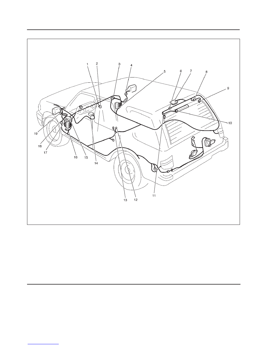
WIRING SYSTEM
Parts Location
D08RX077
Legend
(1) I–17
(2) RR Defogger Switch & Mirror Defogger Switch
(3) H–33
(4) D–12
(5) H–19
(6) H–21
(7) Luggage Room Light
(8) H–20
(9) G–9
(10) G–10, G–11
(11) G–12
(12) B–6
(13) B–8
(14) PCM
(15) Relay and Fuse Box
(16) H–31
(17) I–39 (Rear Defogger & Mirror Defogger Relay)
(18) H–28
(19) D–3