Isuzu Rodeo UE. Manual - part 181


  Index      Isuzu     Isuzu Rodeo UE - service repair manual 1999 year


Search            


Content   ..  179  180  181  182   ..


Isuzu Rodeo UE. Manual - part 181


6E1–95

RODEO X22SE 2.2L ENGINE DRIVEABILITY AND EMISSION

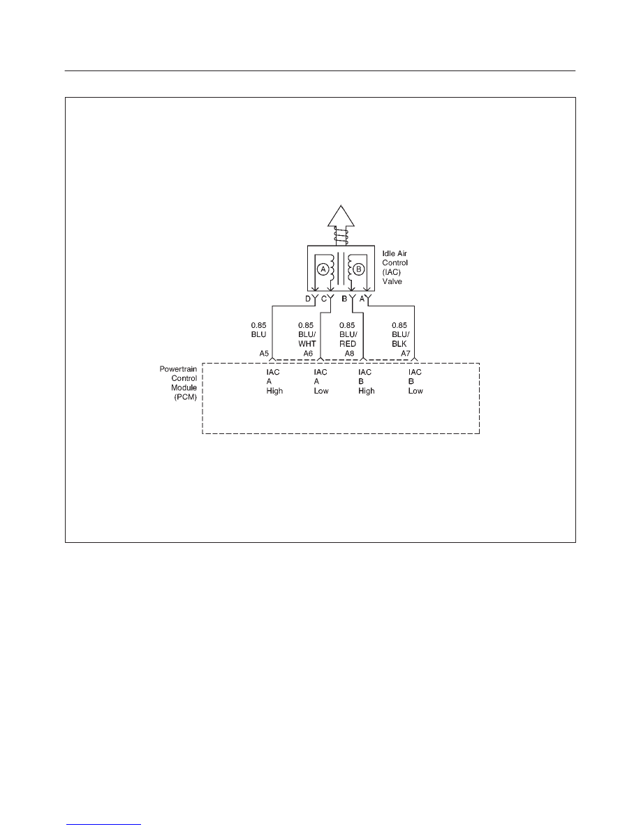
IDLE AIR CONTROL (IAC) SYSTEM CHECK

D06RX041

Circuit Description

The powertrain control module (PCM) controls engine
idle speed with the idle air control (IAC) valve. To increase
idle speed, the PCM retracts the IAC valve pintle away
from its seat, allowing more air to bypass the throttle bore.
To decrease idle speed, it extends the IAC valve pintle
towards its seat, reducing bypass air flow. A Tech 2 will
read the PCM commands to the IAC valve in counts.
Higher counts indicate more air bypass (higher idle).
Lower counts indicate less air is allowed to bypass (lower
idle).

Diagnostic Aids

A slow, unstable, or fast idle may be caused by a non–IAC
system problem that cannot be overcome by the IAC
valve. Out of control range IAC Tech 2 counts will be
above 60 if idle is too low, and zero counts if idle is too

high. The following checks should be made to repair a
non–IAC system problem:

f

Vacuum leak (high idle) – If idle is too high, stop the
engine. Fully extend (low) IAC with the IAC motor
analyzer J 39027–A. Start the engine. If idle speed is
above 800 RPM, locate and correct the vacuum leak,
including the PCV system. Check for binding of the
throttle blade or linkage.

f

Lean heated oxygen sensor signal (high air/fuel ratio)
– The idle speed may be too high or too low. Engine
speed may vary up and down, and disconnecting the
IAC valve does not help. Diagnostic trouble codes
P0131, P0151, P0171, or P0174 may be set. Tech 2
oxygen (O2) voltage will be less than 100 mV (0.1 V).
Check for low regulated fuel pressure, water in fuel, or
a restricted injector.

6E1–96

RODEO X22SE 2.2L ENGINE DRIVEABILITY AND EMISSION

f

Rich heated oxygen sensor signal (low air/fuel ratio) –
The idle speed will be too low. Tech 2 IAC counts will
usually be above 80. The system is obviously rich and
may exhibit black smoke in the exhaust.

f

Tech 2 O2 voltage will be fixed at about 750 mV (0.75
V). Check for high fuel pressure, or a leaking or
sticking injector. A silicon–contaminated heated
oxygen sensor will show an O2 voltage slow to
respond on the Tech 2.

f

Throttle body – Remove the IAC valve and inspect the
bore for foreign material.

f

IAC valve electrical connections – IAC valve
connections should be carefully checked for proper
contact.

f

PCV valve – An incorrect or faulty PCV valve may
result in an incorrect idle speed. Refer to Diagnosis,
Rough Idle, Stalling. 
If intermittent poor driveability or idle symptoms are
resolved by disconnecting the IAC, carefully recheck
the connections and valve terminal resistance, or
replace the IAC.

Test Description

Number(s) below refer to the step number(s) on the
Diagnostic Chart:

1. The IAC motor analyzer J 39027–A is used to

extend and retract the IAC valve. Valve movement
is verified by an engine speed change. If no change
in engine speed occurs, the valve can be resettled
when removed from the throttle body.

2. This step checks the quality of the IAC movement in

step 1. Between 700 revolutions per minute (RPM)
and about 1500 RPM, the engine speed should
change smoothly with each flash of the tester light
in both extend and retract. If the IAC valve is
retracted beyond the control range (about 1500
RPM), it may take many flashes to extend the IAC
valve before engine speed will begin to drop. This is
normal on certain engines. Fully extending the IAC
may cause engine stall. This may be normal.

6. Steps 1 and 2 verified the proper IAC valve

operation. This step checks the IAC circuits. Each
lamp on the noid light should flash red and green
while the IAC valve is cycled. While the sequence of
color is not important, if either light is OFF or does
not flash red and green, check the circuits for faults,
beginning with poor terminal contacts.

Idle Air Control (IAC) System Check


Step

Action

Value(s)

Yes

No

1

1. Ignition OFF.
2. Connect the IAC motor analyzer J 39027–A to the

IAC valve.

3. Set the parking brake.
4. Block the wheels.
5. Turn the air conditioning OFF.
6. Idle the engine in Park (A/T) or Neutral (M/T).
7. Install the Tech 2. Display the RPM.
8. Use the IAC motor analyzer J 39027–A to extend

and retract the IAC valve.

9. The engine speed should decrease and increase as

the IAC is cycled.

Does the RPM change?

Go to Step 2 

Go to Step 3 

2

RPM should change smoothly with each flash of the
IAC motor analyzer J 39027–A light.

Does the RPM change within the range specified?

700–1500

RPM

Go to Step 6 

Go to Step 3 

3

Check the IAC passages.

Are the IAC passages blocked?

Go to Step 4 

Go to Step 5 

4

Clear any obstruction from the IAC passages.

Is the action complete?

Verify repair

5

Replace the IAC. Refer to On–Vehicle Service, Idle Air
Control Valve.

Is the action complete?

Verify repair

6E1–97

RODEO X22SE 2.2L ENGINE DRIVEABILITY AND EMISSION

Idle Air Control (IAC) System Check

  (Cont'd)

Step

No

Yes

Value(s)

Action

6

1. Install the appropriate IAC noid light from J

39027–A into the powertrain control module
harness.

2. Cycle the IAC motor analyzer J 39027–A and

observe the noid lights.

3. Both the lights should cycle red and green, but

never OFF, as the RPM is changed over its range.

Do the noid lights cycle red and green?

Go to Step 7 

Go to Step 8 

7

1. Use the other connector on the IAC motor analyzer

J 39027–A pigtail.

2. Check the resistance across the IAC coils. Measure

the resistance between terminal A and terminal B.

3. Measure the resistance between terminal C and

terminal D.

Is the resistance within the specified range?

40–80 

W

Go to Step 9 

Go to Step 10

8

If the circuits did not test green and red, check the
following:

f

Faulty connector terminal contacts

f

Open circuits, including connections

f

Circuits shorted to ground or voltage

f

Faulty powertrain control module connector(s) or
powertrain controlmodule.

Are repairs necessary?

Go to Step 13

9

1. Check the resistance between the IAC terminal B

and terminal C.

2. Check the resistance between the IAC terminal A

and terminal D.

Is the resistance infinite?

Go to Step 11

Go to Step 12

10

Replace the IAC. Refer to On–Vehicle Service, Idle Air
Control Valve.

Is the action complete?

Go to Step 7 

11

Check the IAC valve and circuit.

Are the IAC valve and circuit OK?

Refer to

Diagnostic

Aids 

Go to Step 12

12

Replace the IAC. Refer to On–Vehicle Service, Idle Air
Control Valve.

Is the action complete?

Go to Step 9 

13

Repair or replace the faulty component(s).

Is the action complete?

Go to Step 6 

6E1–98

RODEO X22SE 2.2L ENGINE DRIVEABILITY AND EMISSION

EXHAUST GAS RECIRCULATION (EGR) SYSTEM CHECK

D06RX055

Circuit Description

A properly operating exhaust gas recirculation (EGR)
system will directly affect the air/fuel requirements of the
engine. Since the exhaust gas introduced into the air/fuel
mixture is an inert gas (contains very little or no oxygen),
less fuel is required to maintain a correct air/fuel ratio.
Introducing exhaust gas into the combustion chamber
lowers combustion temperatures and reduces the
formation of oxides of nitrogen (NOx) in the exhaust gas.
Lower combustion temperatures also prevent detonation.
If the EGR pintle were to stay closed, the inert exhaust
gas would be replaced with air and the air/fuel mixture
would be leaner. The powertrain control module (PCM)
would compensate for the lean condition by adding fuel,
resulting in higher long term fuel trim values.

Diagnostic Aids

The EGR valve chart is a check of the EGR system. An
EGR pintle constantly in the closed position could cause
detonation and high emissions of NOx. It could also result
in high long term fuel trim values in the open throttle cell,
but not in the closed throttle cell. An EGR pintle constantly
in the open position would cause rough idle. Also, an EGR
valve mounted incorrectly (rotated 180

°

) could cause a

rough idle without setting an EGR DTC. Check for the
following items:

f

EGR passages – Check for restricted or blocked EGR
passages.

f

Manifold absolute pressure sensor – A manifold
absolute pressure sensor may shift in calibration
enough to affect fuel delivery. Refer to Manifold
Absolute Pressure Output Check. 


Content   ..  179  180  181  182   ..