Index Isuzu Isuzu Rodeo UE - service repair manual 1999 year
Search
Content .. 92 93 94 95 ..
Isuzu Rodeo UE. Manual - part 94
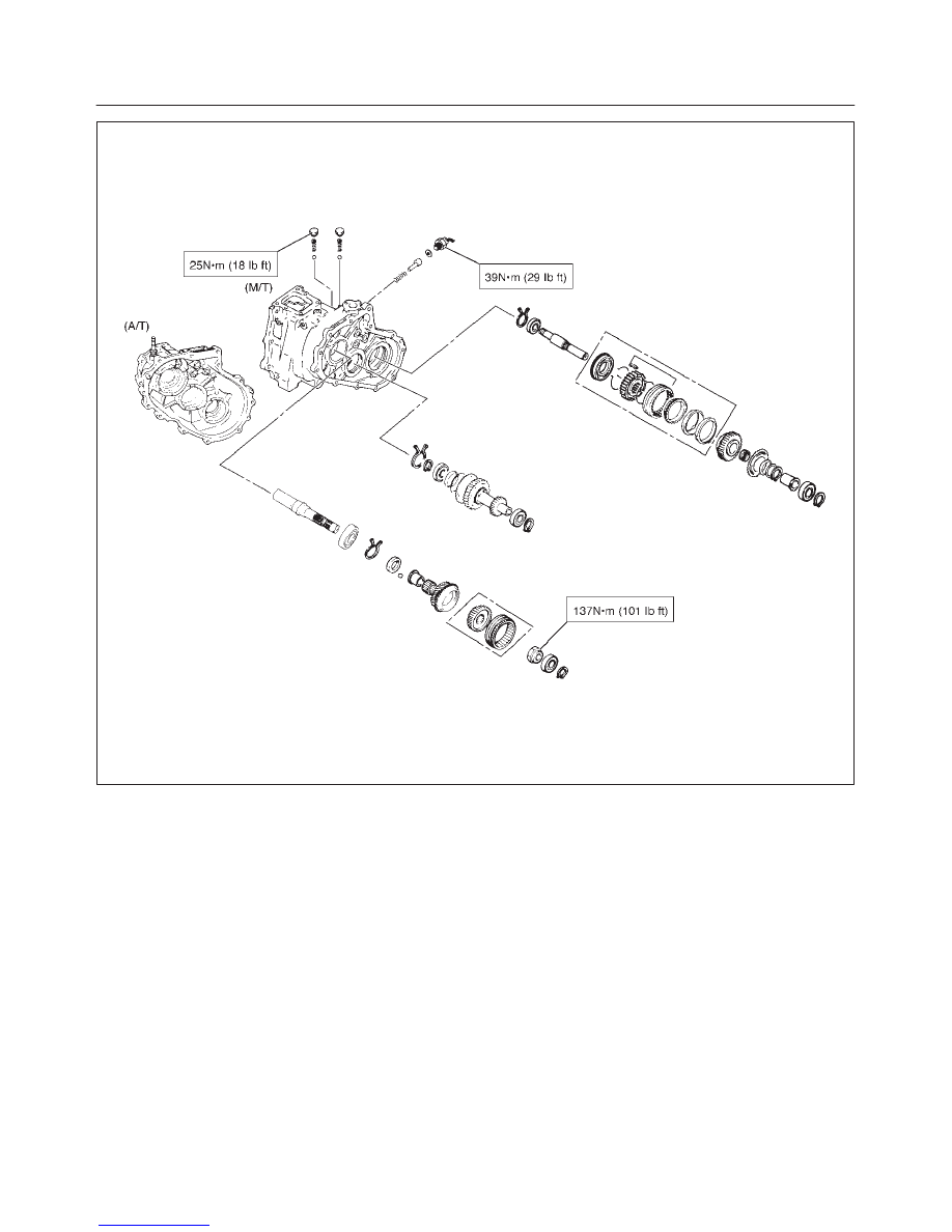
TRANSFER CASE
4D–39
E07RX005