Isuzu Rodeo UE. Manual - part 14
1A–26 HEATING, VENTILATION AND AIR CONDITIONING (HVAC)
Control Panel Illumination Bulb
Control Panel Illumination Bulb and
Associated Parts
865RW003
Legend
(1) Control Lever Assembly
(2) Bulb Socket
(3) Illumination Bulb
Removal
1. Disconnect the battery ground cable.
2. Remove control lever assembly.
f
Refer to Control Lever Assembly in this section.
3. Pull out the bulb socket from the panel by turning it
counterclockwise.
4. Pull the illumination bulb from the socket.
Installation
To install, follow the removal steps in the reverse order.
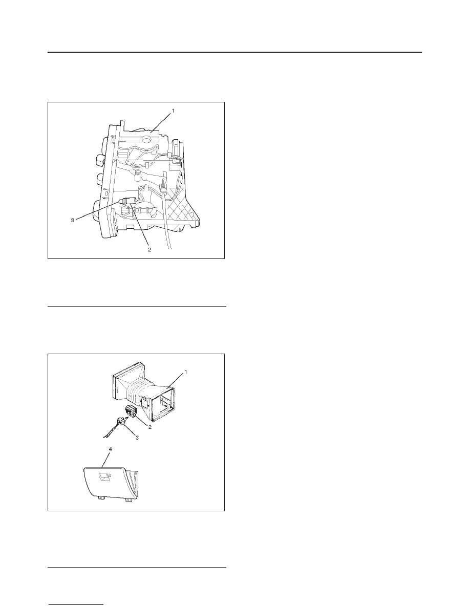
Resistor
Resistor and Associated Parts
840RW001
Legend
(1) Duct (Heater only)
(2) Resistor
(3) Resistor Connector
(4) Glove Box
Removal
1. Disconnect the battery ground cable.
2. Remove glove box.
3. Remove resistor connector.
4. Remove duct (heater only).
5. Remove resistor.
Installation
To install, follow the removal steps in the reverse order.