Isuzu D-Max / Isuzu Rodeo (TFR/TFS). Manual - part 861


  Index      Ford     Isuzu D-Max / Isuzu Rodeo TFR/TFS series - service repair manual 1997-2003 year


Search            


Content   ..  859  860  861  862   ..


Isuzu D-Max / Isuzu Rodeo (TFR/TFS). Manual - part 861


6E–173

3.2L ENGINE DRIVEABILITY AND EMISSIONS

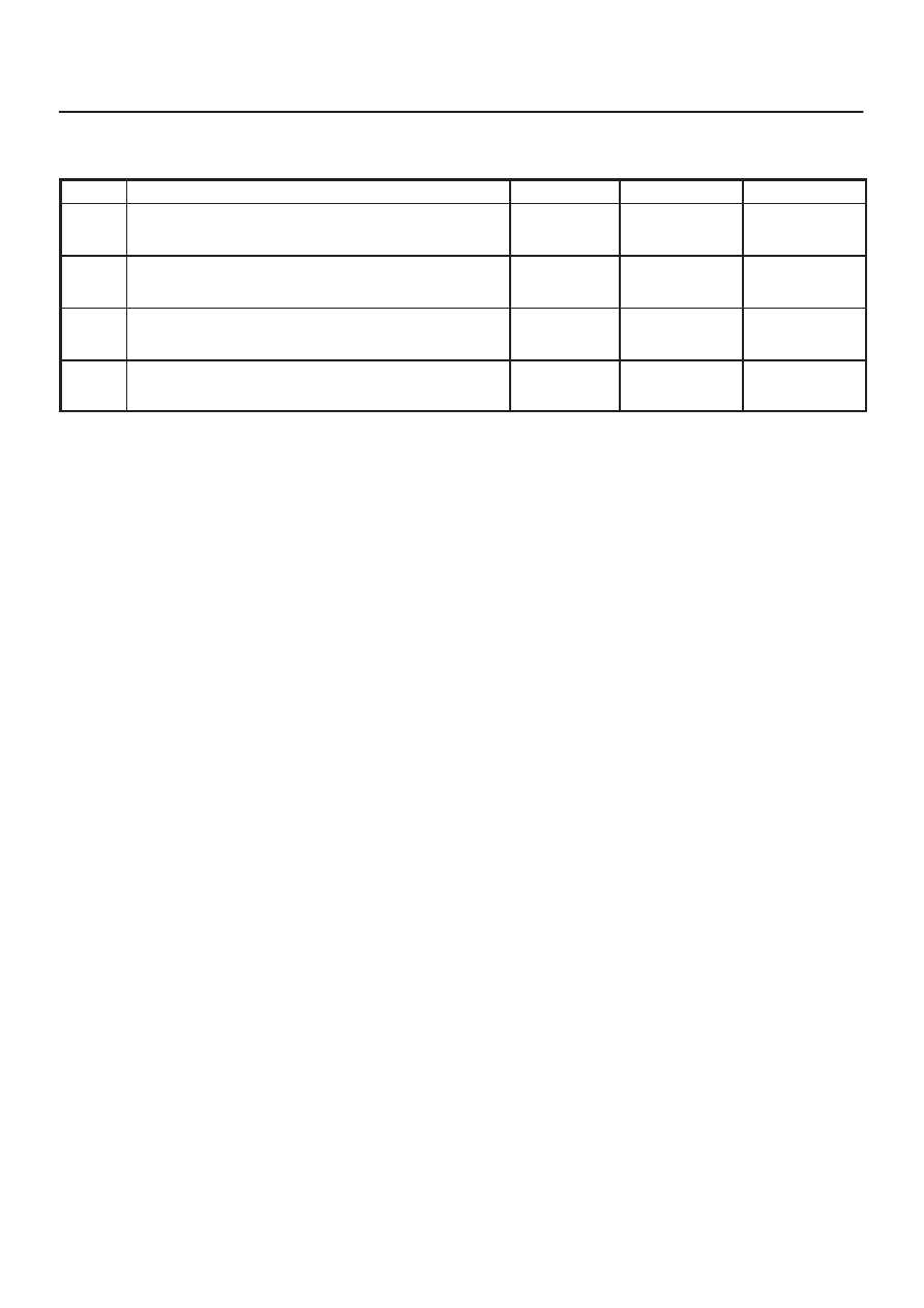
DTC P0355 – Ignition 5 Control Circuit

  (Cont'd)

Step

No

Yes

Value(s)

Action

10

Check ignition control circuit 5 for short to voltage.

Was a problem found?

Verify repair

Go to 

Step 13

11

Check for an open ignition control circuit 5.

Was the ignition control circuit open?

Go to 

Step 12

Go to 

Step 13

12

Repair the open ignition control circuit.

Is the action complete?

Verify repair

13

Replace the ECM.

Is the action complete?

Verify repair

6E–174 3.2L ENGINE DRIVEABILITY AND EMISSIONS

Diagnostic Trouble Code (DTC) P0356 (Flash DTC=42) Ignition 6 Control 

Circuit

060RW075

Circuit Description

The engine control module’s (ECM) control circuit 6
provides a zero-volt or a 5-volt output signal to the ignition
coil.  The normal voltage on the circuit is zero volts.  When
the ignition coil receives the 5-volt signal from the ECM, it
provides a ground path for the B+ supply to the primary
side of the number 6 ignition coil.  When the ECM shuts off
the 5 volts to the ignition coil, the ignition coil turns “OFF.”
This causes the ignition coil primary magnetic field to
collapse, producing a voltage in the secondary coil which
fires the spark plug.
The circuit between the ECM and ignition coil is monitored
for an open circuit, short to voltage, and short to ground.
When the ECM detects a problem on ignition control
circuit 6, it will set a DTC P0356.

Conditions for Setting the DTC

D

The ignition is “ON.”

D

The engine is turning, determined by the crankshaft
position input signal.

D

Engine running speed is between 200 r.p.m and 850
r.p.m.

D

Spark signal don’t present 6 samples of continuous.

Action Taken When the DTC Sets

D

The ECM will illuminate the malfunction indicator lamp
(MIL) the first time the fault is detected.

D

The ECM will store conditions which were present
when the DTC was set as Freeze Frame and in the
Failure Records data.

Conditions for Clearing the MIL/DTC

D

The ECM will turn the MIL “OFF” on the third
consecutive trip cycle in which the diagnostic has been
run and the fault condition is no longer present.

D

A history DTC P0356 will clear after 40 consecutive
warm-up cycles occur without a fault.

6E–175

3.2L ENGINE DRIVEABILITY AND EMISSIONS

D

DTC P0356 can be cleared by using the Tech 2 “Clear
Info” function or by disconnecting the ECM battery
feed.

Diagnostic Aids

Check for the following conditions:

D

Poor connection at ECM – Inspect the harness
connectors for backed-out terminals, improper mating,
broken locks, improperly formed or damaged
terminals, and poor terminal-to-wire connections.

D

Damaged harness – Inspect the wiring harness for
damage.  If the harness appears to be OK, observe the
Tech 2 display related to DTC P0356 while moving the
connector and wiring related to the ignition system.  A
change in the display will indicate the location of the
fault.

Reviewing the Failure Records vehicle mileage since the
diagnostic test last failed may help determine how often
the condition that caused the DTC to be set occurs.  This
may assist in diagnosing the condition.

DTC P0356 – Ignition 6 Control Circuit


Step

Action

Value(s)

Yes

No

1

Was the “On-Board Diagnostic (OBD) System Check”
performed?

Go to 

Step 2

Go to 

OBD

System

Check

2

1. Ignition “ON,” engine “OFF.”
2. Review and record Tech 2 Failure Records data.
3. Operate the vehicle within Failure Record

conditions as noted.

4. Use a Tech 2 to monitor the “DTC” information for

DTC P0356 until the DTC P0356 test runs.

5. Note the test result.

Does the Tech 2 indicate DTC P0356 failed this ignition
cycle?

Go to 

Step 3

Go to

Diagnostic

Aids

3

Check for faulty connection at ignition coil.

Was a problem found?

Verify repair

Go to 

Step 4

4

Check for faulty connection at ECM connector.

Was a problem found?

Verify repair

Go to 

Step 5

5

1. Ignition “ON,” engine “OFF.”
2. Back probe the ignition control circuit 6 at the ECM

with a DVM.

Is the voltage near the specified value?

25-55 mV

Go to 

Step 6

Go to 

Step 9

6

1. Ignition “ON,” engine running.
2. Back probe the ignition control circuit at the ECM for

the cylinder being tested.

Is the voltage in the specified range, rapidly toggling
back and forth to a reading 20-50 mV higher?

100-180 mV

Go to 

Step 7

Go to 

Step 13

7

1. Ignition “OFF.”
2. Disconnect the 3-pin and 5-pin connectors at the

ignition coil.

3. Check ignition control circuit 6 voltage at the ignition

coil connector while cranking the engine.

Does the voltage measure between the specified
values?

200-1200 mV

Go to 

Step 8

Go to 

Step 11

8

Replace the ignition coil.

Is the action complete?

Verify repair

9

1. Ignition “OFF.”
2. Disconnect the ECM and the ignition coil.
3. Check ignition control circuit 6 for short to ground.

Was a problem found?

Verify repair

Go to 

Step 10

6E–176 3.2L ENGINE DRIVEABILITY AND EMISSIONS

DTC P0356 – Ignition 6 Control Circuit

  (Cont'd)

Step

No

Yes

Value(s)

Action

10

Check ignition control circuit 6 for short to voltage.

Was a problem found?

Verify repair

Go to 

Step 13

11

Check for an open ignition control circuit 6.

Was the ignition control circuit open?

Go to 

Step 12

Go to 

Step 13

12

Repair the open ignition control circuit.

Is the action complete?

Verify repair

13

Replace the ECM.

Is the action complete?

Verify repair


Content   ..  859  860  861  862   ..