Isuzu D-Max / Isuzu Rodeo (TFR/TFS). Manual - part 843
6E–101
3.2L ENGINE DRIVEABILITY AND EMISSIONS
Diagnostic Trouble Code (DTC) P0118 (Flash DTC=14) ECT Sensor Circuit High
Voltage
060RW072
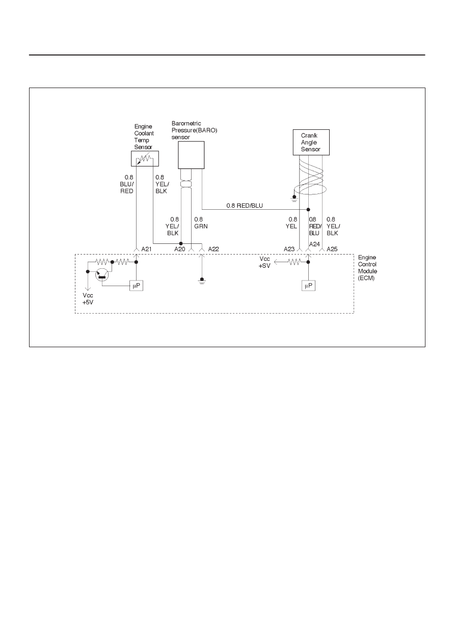
Circuit Description
The engine coolant temperature (ECT) sensor is a
thermistor mounted in on a coolant crossover pipe at the
rear of the engine. The Engine Control Module ECM
applies a voltage (about 5 volts) through a pull-up resistor
to the ECT signal circuit. When the engine coolant is cold,
the sensor (thermistor) resistance is high, therefore the
ECM will measure a high signal voltage. As the engine
coolant warms, the sensor resistance becomes less, and
the ECT signal voltage measured at the ECM drops. With
a fully warmed-up engine, the ECT signal voltage should
measure about 1.5 to 2.0 volts.
Conditions for Setting the DTC
D
Ignition SW is ON.
D
The ECT sensor voltage more than 5000m volts.
D
Above conditions present for at least 5 second.
Action Taken When the DTC Sets
D
The ECM will illuminate the malfunction indicator lamp
(MIL) the first time the fault is detected.
D
The ECM will substitute the ECT reading with a default
engine coolant temperature value. The default value
is based on start-up intake air temperature and running
time.
D
The ECM will store conditions which were present
when the DTC was set as Freeze Frame and in the
Failure Records data.
Conditions for Clearing the MIL/DTC
D
The ECM will turn the MIL “OFF” on the third
consecutive trip cycle during which the diagnostic has
been run and the fault condition is no longer present.
D
A history DTC P0118 will clear after 40 consecutive
warm-up cycles have occurred without a fault.
D
DTC P0118 can be cleared by using the Tech 2 “Clear
Info” function or by disconnecting the ECM battery
feed.
Diagnostic Aids
Check for the following conditions:
D
Poor connection at ECM – Inspect harness connectors
for backed-out terminals, improper mating, broken
locks, improperly formed or damaged terminals, and
poor terminal-to-wire connection.
D
Damaged harness – Inspect the wiring harness for
damage. If the harness appears to be OK, observe the
ECT display on the Tech 2 while moving connectors
and wiring harnesses related to the ECT sensor. A
change in the ECT display will indicate the location of
the fault.
If DTC P0118 cannot be duplicated, the information
included in the Failure Records data can be useful in
determining vehicle mileage since the DTC was last set.
If it is determined that the DTC occurs intermittently,
performing the DTC P1115 Diagnostic Chart may isolate
the cause of the fault.