Isuzu D-Max / Isuzu Rodeo (TFR/TFS). Manual - part 840


  Index      Ford     Isuzu D-Max / Isuzu Rodeo TFR/TFS series - service repair manual 1997-2003 year


Search            


Content   ..  838  839  840  841   ..


Isuzu D-Max / Isuzu Rodeo (TFR/TFS). Manual - part 840


6E–89

3.2L ENGINE DRIVEABILITY AND EMISSIONS

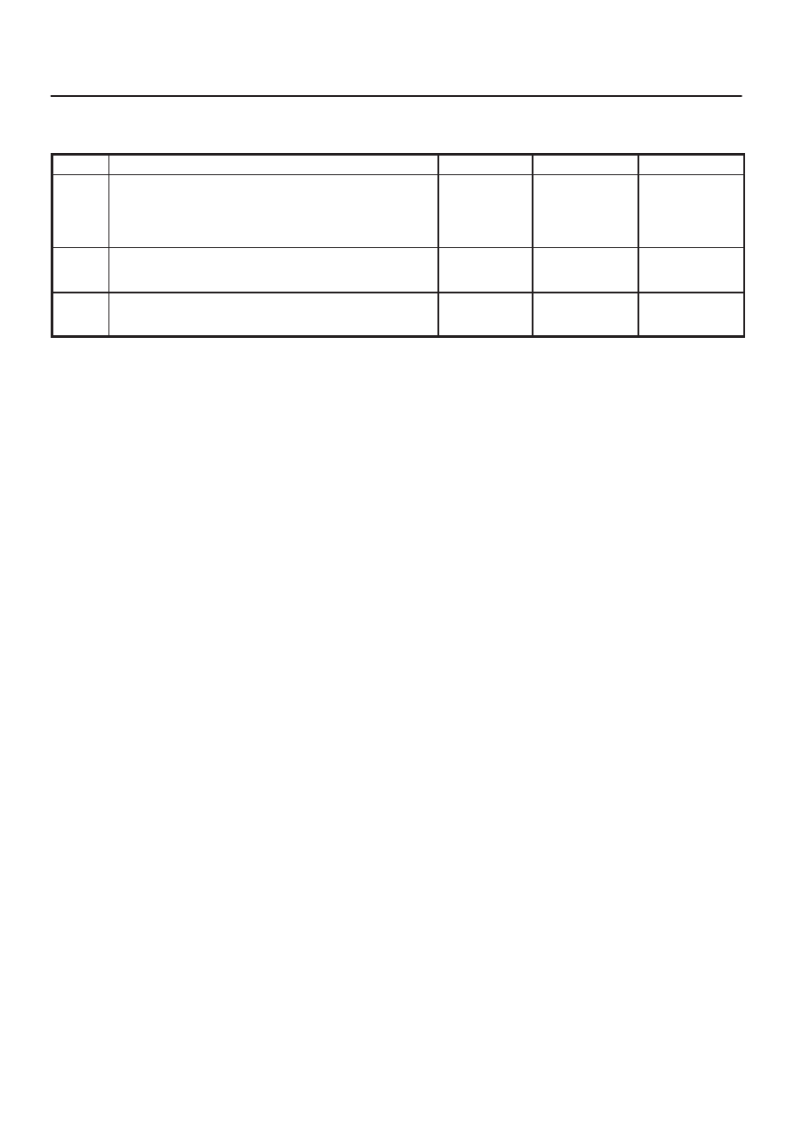
DTC P0107 – BARO Sensor Circuit  Low Voltage

  (Cont'd)

Step

No

Yes

Value(s)

Action

9

Check the BARO sensor signal circuit for a poor
connection at the ECM and the BARO sensor; replace
the terminal if necessary.

Did the terminal require replacement?

Verify repair

Go to 

Step 11

10

Replace the BARO sensor.

Is the action complete?

Verify repair

11

Replace the ECM.

Is the action complete?

Verify repair

6E–90

3.2L ENGINE DRIVEABILITY AND EMISSIONS

Diagnostic Trouble Code (DTC) P0108 (Flash DTC=33) BARO Sensor Circuit

Hight Voltage

060RW072

Circuit Description

The barometric pressure (BARO) sensor responds to
changes in intake manifold pressure (vacuum).  The
BARO sensor signal voltage to the Engine Control
Module ECM varies from below 2 volts at idle (high
vacuum) to above 4 volts with the key “ON,” engine not
running or at wide- open throttle (low vacuum).
The ECM monitors the BARO signals for voltages outside
the normal range of the BARO sensor.  If the ECM detects
a BARO signal voltage that is excessively high, DTC
P0108 will be set.

Conditions for Setting the DTC

D

Ignition SW is ON.

D

The BARO sensor voltage more than 5100V.

D

Above conditions present for at least 19 second.

Action Taken When the DTC Sets

D

The ECM will illuminate the malfunction indicator lamp
(MIL) the first time the fault is detected.

D

The ECM will default to a BARO value of 79.3 kpa.

D

The ECM will store conditions which were present
when the DTC was set as Freeze Frame and in the
Failure Records data.

Conditions for Clearing the MIL/DTC

D

The ECM will turn the MIL “OFF” on the third
consecutive trip cycle during which the diagnostic has
been run and the fault condition is no longer present.

D

A history DTC P0108 will clear after 40 consecutive
warm-up cycles have occurred without a fault.

D

DTC P0108 can be cleared by using the Tech 2 “Clear
Info” function or by disconnecting the ECM battery
feed.

Diagnostic Aids

Check for the following conditions:

D

Poor connection at ECM – Inspect harness connectors
for backed-out terminals, improper mating, broken
locks, improperly formed or damaged terminals, and
poor terminal-to-wire connection.

D

Damaged harness – Inspect the wiring harness for
damage.  If the harness appears to be OK, observe the
BARO display on the Tech 2 while moving connectors
and wiring harnesses related to the sensor.  A change
in the display will indicate the location of the fault.

If DTC P0108 cannot be duplicated, the information
included in the Failure Records data can be useful in
determining vehicle mileage since the DTC was last set. If
it is determined that the DTC occurs intermittently,
performing the DTC P1108 Diagnostic Chart may isolate
the cause of the fault.

6E–91

3.2L ENGINE DRIVEABILITY AND EMISSIONS

DTC P0108 – BARO Sensor Circuit High Voltage


Step

Action

Value(s)

Yes

No

1

Was the “On-Board Diagnostic (OBD) System Check”
performed?

Go to 

Step 2

Go to 

OBD

System

Check

2

1. If the engine idle is rough, unstable or incorrect,

repair the idle problem before using this chart. Refer
to 

Symptoms section.

2. With the engine idling, note the BARO value on the

Tech 2.

Is the BARO reading above the specified value?

90 kpa

Go to 

Step 4

Go to 

Step 3

3

1. Ignition “ON,” engine “OFF.”
2. Review and record Tech 2 Failure Records data.
3. Operate the vehicle within Failure Records

conditions as noted.

4. Using a Tech 2, monitor “ DTC” info for DTC P0108.

Does the Tech 2 indicate DTC P0108 failed this
ignition?

Go to 

Step 4

Refer to

Diagnostic

Aids

4

1. Ignition “OFF.”
2. Disconnect the BARO sensor electrical connector.
3. Ignition “ON.”
4. Note the BARO sensor voltage displayed on the

Tech 2.

Is the BARO sensor voltage at the specified value?

0.0 V 11 kpa

Go to 

Step 5

Go to 

Step 6

5

Probe the sensor ground circuit with a test light to B+.

Is the test light “ON?”

Go to 

Step 7

Go to 

Step 9

6

1. Check the BARO signal circuit for a short to voltage

or a short to the 5 volt reference “A” circuit.

2. If the BARO sensor signal circuit is shorted, repair

circuit as necessary.

Was the BARO sensor signal circuit shorted?

Verify repair

Go to 

Step 11

7

1. Check for a poor sensor ground terminal connection

at the BARO sensor electrical connector.

2. If a problem if found, replace the faulty terminal.

Did the terminal require replacement?

Verify repair

Go to 

Step 8

8

Check for a plugged or leaking vacuum supply to the
BARO sensor.

Is the vacuum supply plugged or leaking?

Verify repair

Go to 

Step 12

9

1. Check for a poor sensor ground terminal connection

at the ECM.

2. If a problem is found, replace the faulty terminal.

Did the terminal require replacement?

Verify repair

Go to 

Step 10

10

1. Check the continuity of the BARO sensor ground

circuit.

2. If the BARO sensor ground circuit measures over 5

ohms, repair open or poor connection.

Was a condition found and corrected?

Verify repair

Go to 

Step 11

6E–92

3.2L ENGINE DRIVEABILITY AND EMISSIONS

DTC P0108 – BARO Sensor Circuit High Voltage

  (Cont'd)

Step

No

Yes

Value(s)

Action

11

Replace the ECM.

Is the action complete?

Verify Repair

12

Replace the BARO sensor.

Is the action complete?

Verify repair


Content   ..  838  839  840  841   ..