Isuzu D-Max / Isuzu Rodeo (TFR/TFS). Manual - part 784


  Index      Ford     Isuzu D-Max / Isuzu Rodeo TFR/TFS series - service repair manual 1997-2003 year


Search            


Content   ..  782  783  784  785   ..


Isuzu D-Max / Isuzu Rodeo (TFR/TFS). Manual - part 784


6A–16

ENGINE MECHANICAL (6VD1 3.2L)

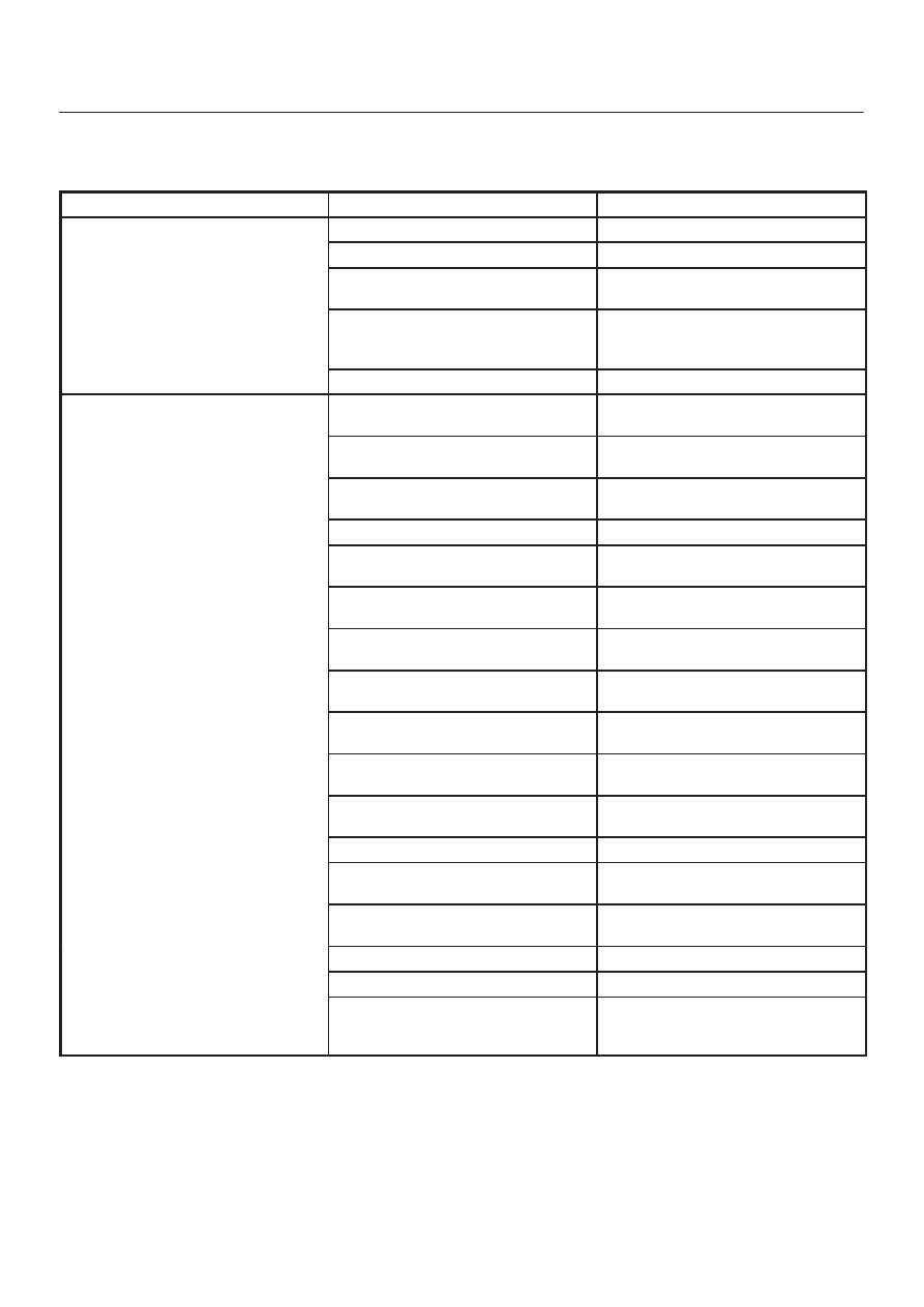
Malfunction Indicator Lamp

The instrument panel “CHECK ENGINE” Malfunction In-
dicator Lamp (MIL) illuminates by self diagnostic system

when the system checks the starting of engine, or senses
malfunctions.

Condition

Possible cause

Correction

“CHECK ENGINE” MIL does not
illuminate at the starting of engine

Bulb defective

Replace

illuminate at the starting of engine

MIL circuit open

Correct or replace

Command signal circuit to operate
self diagnostic system shorted

Correct or replace

Engine Control Module (ECM) cable
loosely connected, disconnected or
defective

Correct or replace

ECM defective

Replace

“CHECK ENGINE” MIL illuminates,
and stays on

Deterioration of heated oxygen
sensor internal element

Replace

Heated oxygen sensor connector
terminal improper contact

Reconnect properly

Heated oxygen sensor lead wire
shorted

Correct

Heated oxygen sensor circuit open

Correct or replace

Deterioration of engine coolant
temperature sensor internal element

Replace

Engine coolant temperature sensor
connector terminal improper contact

Reconnect properly

Engine coolant temperature sensor
lead wire shorted

Correct

Engine coolant temperature sensor
circuit open

Correct or replace

Throttle position sensor open or
shorted circuits

Correct or replace

Deterioration of crankshaft position
sensor

Replace

Crankshaft position sensor circuit
open or shorted

Correct or replace

Vehicle speed sensor circuit open

Correct or replace

Manifold absolute pressure sensor
circuit open or shorted

Correct or replace

Intake air temperature sensor circuit
open or shorted

Correct or replace

Fuel injector circuit open or shorted

Correct or replace

ECM driver transistor defective

Replace ECM

Malfunctioning of ECM RAM
(Random Access Memory) or ROM
(Read Only Memory)

Replace ECM

6A–17

ENGINE MECHANICAL (6VD1 3.2L)

Cylinder Head Cover LH

Removal

1. Disconnect battery ground cable.
2. Remove air cleaner duct assembly.

060RW079

Legend

(1) Positive Crankcase Ventilation Hose Connector
(2) Intake Air Temperature Sensor
(3) Air Cleaner Duct Assembly
(4) Air Cleaner Element

3. Disconnect positive crankcase ventilation hose.
4.  Remove camshaft angle sensor connector.
5.  Remove ground cable fixing bolt on cylinder head

cover.

6. Ignition coil connector and ignition coil.

D

Disconnect the three connectors from the ignition
coils.

D

Remove harness bracket bolt on cylinder head
cover.

D

Remove fixing bolts on ignition coils.

060RW078

Legend

(1) Ignition Coil Connector
(2) Bolt
(3) Ignition Coil Assemblies

7. Remove fixing bolt for fuel injector harness bracket.
8. Remove eight fixing bolts, then the cylinder head

cover.

010RW001

6A–18

ENGINE MECHANICAL (6VD1 3.2L)

Installation

1. Install cylinder head cover.

D

Clean the sealing surface of cylinder head and
cylinder head cover to remove oil and sealing
materials completely.

D

Apply sealant (TB-1207B or equivalent) of bead
diameter 2-3 mm at eight place of arched area of
camshaft bracket on front and rear sides.

D

The cylinder head cover must be installed with in 5
minutes after sealant application to prevent
hardning of sealant.

D

Tighten bolts to the specified torque.

Torque : 9 N·m (0.9 kg·m/80 lb in)

010RW006

2. Install fuel injection harness bracket and tighten bolt

to the specified torque.

Torque : 9 N·m (0.9 kg·m/80 lb in)

3. Connect ignition coil connector and ignition coil, then

tighten bolt to the specified torque.

Torque : 4 N·m (0.4 kg·m/35 lb in)

060RW078

Legend

(1) Ignition Coil Connector
(2) Bolt
(3) Ignition Coil Assembly

4. Connect ground cable and tighten bolts to the

specified torque.

Torque : 9 N·m (0.9 kg·m/80 lb in)

5. Connect camshaft angle sensor connector.
6. Install positive crankcase ventilation hose.
7.  Install air cleaner duct assembly. 

6A–19

ENGINE MECHANICAL (6VD1 3.2L)

Cylinder Head Cover RH

Removal

1. Disconnect battery ground cable.
2. Disconnect ventilation hose from cylinder head cover.
3. Disconnect three ignition coil connectors from ignition

coils and remove harness bracket bolts on cylinder
head cover then remove ignition coil fixing bolts on
ignition coils and remove ignition coils.

4. Remove heater pipe fixing bolts from the bracket.
5. Disconnect fuel injector harness connector then

remove fuel injector harness bracket bolt.

6. Remove eight fixing bolts then the cylinder head

cover.

010RW002

Installation

1. Install cylinder head cover.

D

Clean the sealing surface of cylinder head and
cylinder head cover to remove oil and sealing
materials completely. 
Apply sealant (TB-1207B or equivalent) of bead
diameter 2-3 mm at eight place of arched area of
camshaft bracket on front and rear sides.

D

The cylinder head cover must be installed within 5
minutes after sealant application to prevent
premature hardening of sealant.

D

Tighten bolts to the specified torque.

Torque : 9 N·m (0.9 kg·m/80 lb in)

014RW019

2. Install exhaust gas recirculation pipe and tighten to

specified torque.

Torque:
Exhaust manifold side: 28 N·m (2.9 kg·m/21 lb ft)
Flare nut: 44 N·m (4.5 kg·m/33 lb ft)
Cylinder head side: 25 N·m (2.6 kg·m/18 lb ft)

3. Tighten fuel injector harness bracket bolts to

specified torque then reconnect fuel injector harness
connector.

Torque : 7.8 N·m (0.8 kg·m/5.7 lb ft)

4. Install heater pipe bolt to the specified torque.

Torque : 21 N·m (2.1 kg·m/15 lb ft)

5. Connect ignition coil connector and tighten ignition

coil fixing bolts to specified torque.

Torque : 4 N·m (0.4 kg·m/35 lb in)

6. Connect ventilation hose to cylinder head.


Content   ..  782  783  784  785   ..