Isuzu D-Max / Isuzu Rodeo (TFR/TFS). Manual - part 600


  Index      Ford     Isuzu D-Max / Isuzu Rodeo TFR/TFS series - service repair manual 1997-2003 year


Search            


Content   ..  598  599  600  601   ..


Isuzu D-Max / Isuzu Rodeo (TFR/TFS). Manual - part 600


ENGINE ELECTRICAL  6D – 7 


SYMBOLS AND ABBREVIATIONS 


DESCRIPTION 

The symbols and abbreviations used in the circuit diagram 
make the diagram easier to read and understand. 


SYMBOLS 

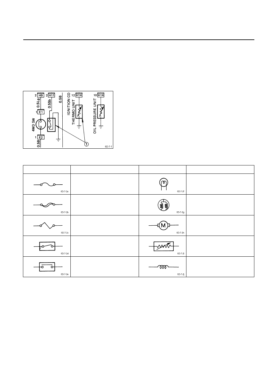
The illustration at the left shows a typical symbol 



 used 

in circuit diagrams. 
Refer to the following table. 


SYMBOL AND MEANING 

Symbol Meaning Symbol Meaning 


Fuse 

Single filament bulb 


Main fuse 

Double filament bulb 


Fusible link wire 

Motor 


Switch 

Variable resistor 


Switch 

Coil (Inductor) 


6D – 8  ENGINE ELECTRICAL 


Symbol Meaning Symbol Meaning 


Contact wiring 


Battery 

Relay 

Note: 
Relay contact shown in the 
wiring diagram indicates 
condition before actuation. 


Diode 

Connector 


Electronic part 

Light emitting diode 


Resistor 

Reed switch 


Speaker 

Condenser 


ABBREVIATIONS 

The illustration at the left shows a typical abbreviation 

 

used in circuit diagrams. 
These same abbreviations may also appear in the next. 
Refer to the following table. 


ABBREVIATION AND MEANING 

Abbreviation Meaning Abbreviation Meaning 

RH 

LH 

SW 

M/T 

A/T 

FT 

RR 

FLW 

TEMP 

ECM 

Right-hand side 
Left-hand side 
Switch 
Manual transmission 
Automatic transmission 
Front 
Rear 
Fusible link wire 
Temperature 
Electronic control module 

STD 

OPT 

W/ 

WO/ 

OD 

ACC 

A/C 

ATF 

VSV 

Standard equipment 
Optional equipment 
With 
Without 
Overdrive 
Accessories 
Air conditioner 
Automatic transmission fluid 
Vacuum switching valve 


ENGINE ELECTRICAL  6D – 9 


TORQUE SPECIFICATIONS 

GENERATOR  

kg

 m(ft. lbs/N m)


STARTER MOTOR  

kg

 m(ft. lbs/N m)


0.65 

±±±± 0.5(4.7 ±±±± 3.6/6.3 ±±±± 4.9) 

6D – 10  ENGINE ELECTRICAL 


GENERATOR 


 REMOVAL AND INSTALLATION 

Read this Section carefully before performing any removal and installation procedure. This Section gives you 
important points as well as the order of operation. Be sure that you understand everything in this Section before you 
begin. 


Important Operations-Removal 

Cooling Fan Belt 

1)  Disconnect the battery cables at the battery terminals.
2)  Loosen and remove the fan belt adjusting plate bolts. 
3)  Remove the fan belt from the generator drive pulley. 


Generator 

Remove the generator bolt and the generator from the 
bracket. 


Important Operations-Installation 

Follow the removal procedure in the reverse order to 
perform the installation procedure. Pay careful attention to 
the important points during the installation procedure. 


Generator 

1)  Install the generator to the bracket. 
2)  Tighten the generator bolt to the specified torque. 


Generator Bolt Torque 

kg·m (lb·ft/N·m)





1.9 

± 0.5 (13.7 ± 3.6/18.6 ± 4.9) 


‚


4.1 

± 0.6 (29.6 ± 4.3/40.2 ± 5.9) 


066L200001 


Content   ..  598  599  600  601   ..