Isuzu D-Max / Isuzu Rodeo (TFR/TFS). Manual - part 574


  Index      Ford     Isuzu D-Max / Isuzu Rodeo TFR/TFS series - service repair manual 1997-2003 year


Search            


Content   ..  572  573  574  575   ..


Isuzu D-Max / Isuzu Rodeo (TFR/TFS). Manual - part 574


6A – 134  ENGINE MECHANICAL

Important Operations

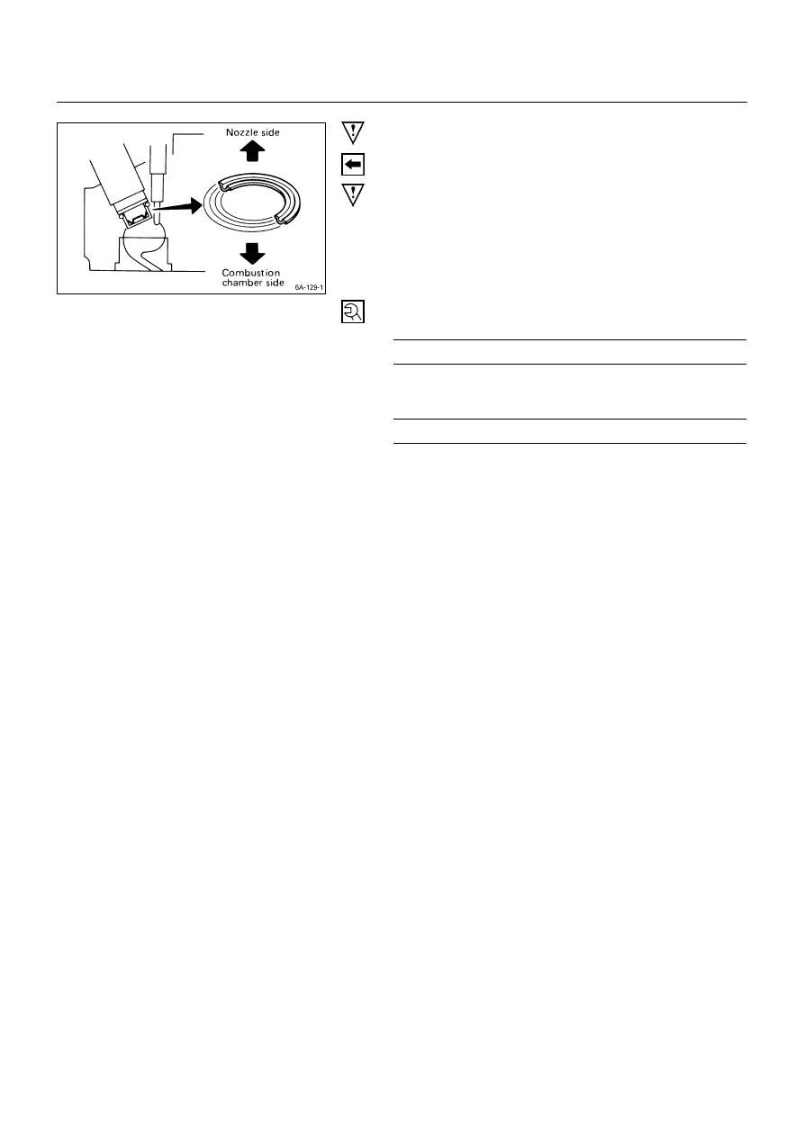
39a.Nozzle Holder Assembly (4JG2T Engine)

Install the parts in sequence of corrugated washer, nozzle
gasket and nozzle holder.

Do not reuse the corrugated washer and nozzle gasket.

Use the new one.

The corrugated washer should be installed with blue color
painted side turned to the nozzle.

Tighten the nozzle holder.

Nozzle Holder Torque

kg·m (lb.ft/N·m)


6.5 

±

 0.5 (47.0 

±

 3.6/63.7 

±

 4.9)


Install the leak-off pipe via the copper gasket.

Leak Off Pipe Torque

kg·m (lb.ft/N·m)


3.5 – 4.7 (25.3 – 34.0/34.3 – 46.1)


ENGINE MECHANICAL   6A – 135

Note on Valve Clearance Adjustment

Valve clearances must be adjusted before the cylinder
head cover is reinstalled.

Refer to “Valve Clearance Adjustment” in the “Servicing”
Section of this Manual.

40. Cylinder Head Cover

1)  Apply engine oil to the rocker arm and the valve

spring.

2)  Install the cylinder head cover gasket to the head

cover.

Check to see that the head cover gasket has no loose
areas.

3) Tighten the cylinder head cover nuts in the numerical

order shown in the illustration.

Cylinder Head Cover Bolt Torque

kg·m (lb.ft/N·m)


1.3 

±

 0.5 (9.4 

±

 3.6/12.7 

±

 4.9)


4) Connect the PCV hose to the cylinder head cover.

6A – 136  ENGINE MECHANICAL 


 INTERNAL PARTS 

MAJOR COMPONENTS 


Reassembly Steps-1 (Gear Drive Model) 


J

 1. 

Timing gear case 


J

 2. 

Camshaft thrust plate 


J

 3. Camshaft timing gear 


014RY00048

ENGINE MECHANICAL   6A – 137 


Reassembly Steps-2 (Gear Drive Model)


J

 4. 

Crankshaft timing gear 


J

 9. 

Injection pump 


J

 5. 

Idler gear shaft 


J

 10. 

Timing gear case cover 


J

 6. Idler gear “A” 


11. 

Space rubber 


J

 7. Idler gear “B” and shaft 


12. 

Gear case cover upper cover  


J

 7a.  Idler gear “B” and shaft (Scissor 

gear 


and lower cover 


J

 8. 

Timing gear oil pipe (Except 
4JA1TC, 4JH1TC) 


J

 13.  Crankshaft damper pulley 

7a


Content   ..  572  573  574  575   ..