Isuzu D-Max / Isuzu Rodeo (TFR/TFS). Manual - part 389


  Index      Ford     Isuzu D-Max / Isuzu Rodeo TFR/TFS series - service repair manual 1997-2003 year


Search            


Content   ..  387  388  389  390   ..


Isuzu D-Max / Isuzu Rodeo (TFR/TFS). Manual - part 389


7A-104  AUTOMATIC TRANSMISSION (AW30-40LE) 

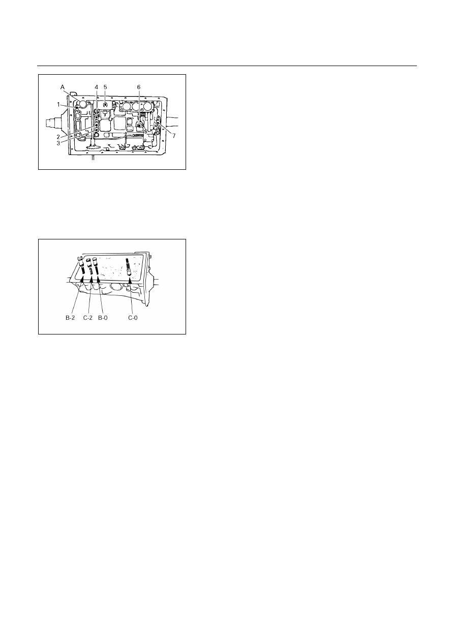
Individual piston operation inspection 

Check for the sound of operation while injecting 
compressed air into the oil hole indicated in the figure. 

1: OD direct clutch 
2: Direct clutch 
3: Forward clutch 
4: OD brake 

5: Second coast brake 
6: Second brake 
7: First and reverse brake 
A: C-0 Accumulator piston 

hole 


240RY00014 


NOTE: 
When inspecting the direct clutch, check with the 
C-0 accumulator piston hole closed. If there is no 
noise, disassemble and check the condition of the 
parts.


240RY00027 


7. Accumulator piston 

Coat the O-ring with ATF and install it to the piston. 
Install the three springs and four accumulator pistons to 
the bore as shown in th figure. 


AUTOMATIC TRANSMISSION (AW30-40LE)  7A-105 


Piston Outer 

diameter Height 

B-2 

36.8 mm (1.449 in) 62.5 mm (2.461 in)

C-2 

36.8 mm (1.449 in) 56.6 mm (2.228 in)

B-0 

31.8 mm (1.252 in) 52.0 mm (2.047 in)

C-0 

29.8 mm (1.173 in) 44.0 mm (1.732 in)


Spring 

Free length 

Outer diameter 

B-2 

70.5 mm (2.276 in) 19.7 mm (0.776 in)

C-2 (Outer) 

68.5 mm (2.697 in) 20.2 mm (0.795 in)

C-2 (Inner) 

20.0 mm (0.787 in) 

12.06 mm  

(0.4748 in) 

B-0 

62.0 mm (2.441 in) 16.0 mm (0.630 in)

C-0 (Outer) 

74.6 mm (2.937 in) 20.9 mm (0.823 in)

C-0 (Inner)) 

46.0 mm (1.811 in) 14.0 mm (0.551 in)


240RY00029 


240RY00010 


240RY00016 


8. Check valve, spring 

Install new check valve and spring. 


240RY00017 


9. Valve body 

Align the groove of the manual valve to the pin of the 
lever. 


7A-106  AUTOMATIC TRANSMISSION (AW30-40LE) 


249R200003 


Connect the throttle cable to the cam. 
Confirm the springs into the accumulator piston are 
installed correctly. 


249R200008 


Install the seventeen bolts. 
NOTE: 
Each bolt length (mm) is indicated in the figure. 
Torque: 10 N
・・・・m (1.0 kg・・・・m/87 Ib・・・・in) 


249R200002 


10. Solenoid wiring 

Coat a new O-ring with ATF, and install it to the 
solenoid wiring. 
Insert the solenoid wiring to the transmission case and 
install the stopper plate. 


249R200001 


Connect the connectors to the solenoid S1, S2 and S3.


249R200005 


11. Oil tube 

Using a plastic hammer, install the two tubes into the
positions shown in the figure. 
CAUTION: 
Be careful not to bend or damage the tubes. 


AUTOMATIC TRANSMISSION (AW30-40LE)  7A-107 


244R200037 


12. Oil strainer assembly 

Install two new gaskets to the oil strainer. 


244R200001 


Install the oil strainer with the gaskets to the valve body. 
Tighten the four bolts. 
Torque: 10 N・・・・m (1.0 kg・・・・m/87 Ib・・・・in) 


240RY00019 


13. Oil pan 

Install two magnets in oil pan. 
NOTE: 
Make sure that the magnet does not interfere with 
the oil tubes.
 
Remove any gasket material and be careful not to drop 
oil on the contacting surfaces of the transmission case 
and oil pan. 
Apply liquid gasket (TB1281 or its equivalent) to the oil 
pan as shown in the figure. 
NOTE: 
Install the oil pan as soon as the seal gasket is 
applied.


240RY00020 


Install and tighten the nineteen bolts. 
Torque: 8 N・・・・m (0.8 kg・・・・m/69 Ib・・・・in) 


Content   ..  387  388  389  390   ..