Isuzu D-Max / Isuzu Rodeo (TFR/TFS). Manual - part 226
ENGINE DRIVEABILITY AND EMISSIONS
6E–145
6
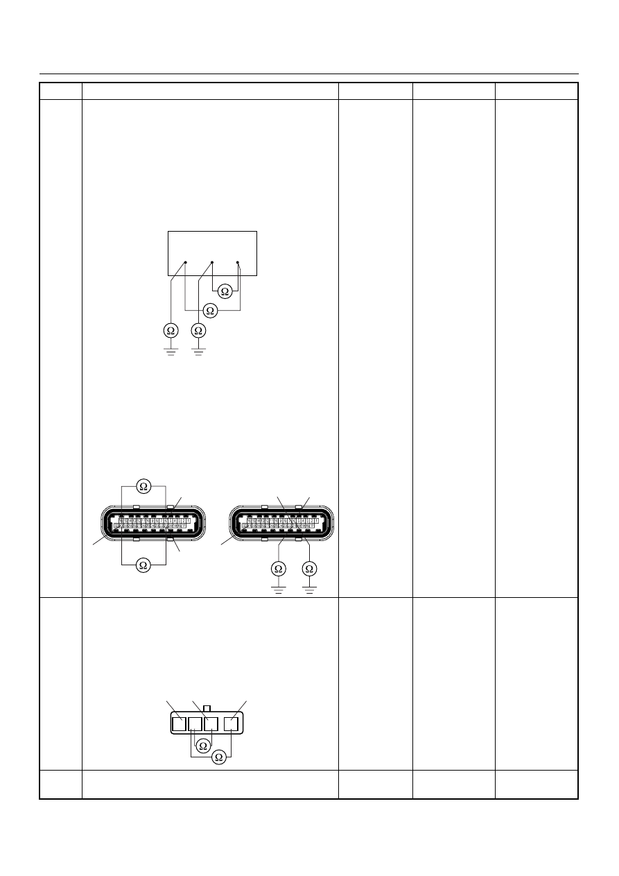
Using the DVM and check the O
2
sensor circuit.
Breaker box is available:
1. Ignition “Off”, engine “Off”.
2. Install the breaker box as type A. (ECM
disconnected) Ref. 6E-80.
3. Disconnect the O
2
sensor.
4. Check the circuit for short to heater ground or
short to ground circuit.
Was the problem found?
Breaker box is not available:
1. Ignition “Off”, engine “Off”.
2. Disconnect the O
2
sensor connector and ECM
connector.
3. Check the circuit for short to heater ground or
short to ground circuit.
Was the problem found?
—
Repair faulty
harness and
verify repair
Go to Step 15
7
Using the DVM and check the O
2
sensor circuit.
1. Ignition “Off”, engine “Off”.
2. Disconnect the the O
2
sensor connector.
3. Check the circuit for short to heater ground circuit.
Was the DVM indicated specified value?
No continuity
Go to Step 9
Go to Step 8
8
Repair the short to heater ground circuit.
Was the problem found?
—
Verify repair
Go to Step 15
Step
Action
Value(s)
Yes
No
38
53
63
31
21
6
C56(J2)
31
21
6
C56(J2)
1
2
4
1
2
3
4
O
2
Sensor