Isuzu D-Max / Isuzu Rodeo (TFR/TFS). Manual - part 1899


  Index      Ford     Isuzu D-Max / Isuzu Rodeo TFR/TFS series - service repair manual 1997-2003 year


Search            


Content   ..  1897  1898  1899  1900   ..


Isuzu D-Max / Isuzu Rodeo (TFR/TFS). Manual - part 1899


7A4-28  UNIT REPAIR (JR405E) 
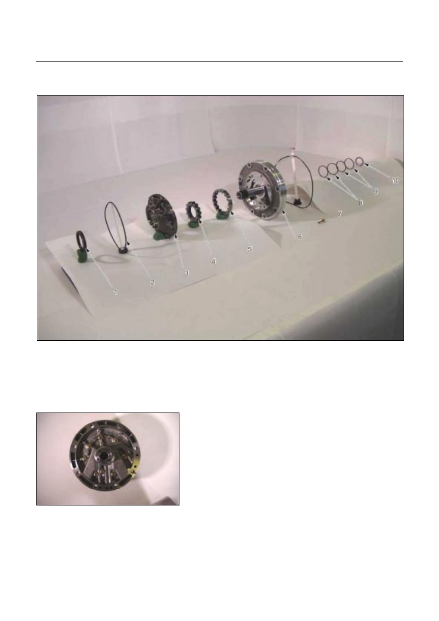


OIL PUMP ASSEMBLY 


01PUMP32 

Legend 


1. Oil seal 


2. O-ring (small) 


3. Oil pump housing 

 4. 

Inner 

rotor 


5. Outer rotor 


6. Oil pump cover 


7. O-ring (large) 


8. Seal ring (large) 


9. Seal ring (small) 

 10. 

Bearing 

race 


02PUMP07 


Disassembly steps 

1. Oil pump cover 

2. Oil pump housing 

  Loosen the 8 bolts evenly a little at a time. 


UNIT REPAIR (JR405E)  7A4-29 


04PUMP10 


  Separate the oil pump cover from the oil pump housing 

by tapping on each of the bolts with a plastic hammer. 


06PUMP13 


3. Inner rotor 

Remove the inner rotor from the oil pump housing. 


07PUMP14 


4. Outer rotor 

Remove the outer rotor form the oil pump housing. 


15PUMP18 


5. O-ring (small) 

Remove the O-ring (small) from the oil pump housing. 


10PUMP19 


6. Oil seal 

Remove the oil seal from the oil pump housing. 


7A4-30  UNIT REPAIR (JR405E) 


08PUMP09 


7. O-ring (large) 

Remove the O-ring (large) from the oil pump cover. 


09PUMP05 


8. Seal ring 

Remove the 4 seal rings from the oil pump cover. 


11PUMP43 


Inspection 

Oil pump cover 

  Install new seal rings to the oil pump cover. 

NOTE: 
The seal ring  with the large inside diameter fits into the 
primary mating surface of the cover. 

  Measure the gap between the seal ring and the seal ring 

groove. 

If the measured gap is outside the specified range, the 

oil pump cover must be replaced. 

Seal ring and seal ring groove gap: 0.10

∼∼∼∼

0.25 mm  

(0.0039

∼∼∼∼

0.0098 in)


12PUMP45 


Inner rotor 

  Install the inner rotor to the oil pump housing. 

  Use a straight edge to measure the side clearance 

between the oil pump housing and the inner rotor. 

If the measured clearance is outside the specified 

range, the inner rotor must be replaced. 

Oil pump housing and inner rotor side clearance:  

0.02~0.04 mm (0.0008~0.0016 in)  


UNIT REPAIR (JR405E)  7A4-31 


13PUMP46 


Outer rotor 

  Install the outer rotor to the oil pump housing. 

  Measure the gap between the outer rotor and the 

crescent. 

If the measured gap is outside the specified range, the 

outer rotor must be replaced. 

Outer rotor and crescent gap: 

0.02~0.15 mm (0.0008~0.0059 in)  


14PUMP28 


Reassembly steps 

Coat the parts with ATF before installing them. 
1. Oil seal 

  Use the oil seal installer to install new oil seal to the oil 

pump housing. 

Oil seal installer: 5-8840-2761-0 


15PUMP18 


2. O-ring (small) 

Install new O-ring (small) to the oil pump housing. 


16PUMP29 


3. Outer rotor 

4. Inner rotor 

Install the outer rotor and the inner rotor to the oil pump

housing. 


17PUMP42 


NOTE: 
The identification mark on the inner rotor must be facing 
the inside of the oil pump housing. 


Content   ..  1897  1898  1899  1900   ..