Content .. 1801 1802 1803 1804 ..
Isuzu D-Max / Isuzu Rodeo (TFR/TFS). Manual - part 1803
UNIT REPAIR (JR405E) 7A4-79
38OUTPUT25
29ASSY089
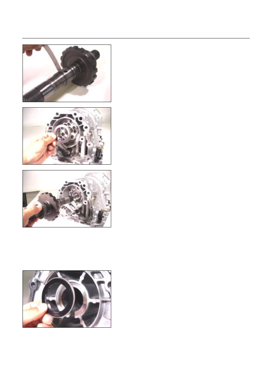
18.Output shaft
•
Install a new seal ring to the output shaft assembly.
•
Measure the gap between the seal ring and the ring
groove.
If the gap is outside the specified range, the output shaft
must be replaced.
Seal ring and ring groove gap:
0.10~0.25 mm (0.0039~0.0098 in)
•
Install the bearing to the case.
NOTE:
••••
Apply Vaseline to the bearing (with bearing race).
••••
The black side (bearing race) of the bearing must be
visible.
40ASSY091
•
Push the output shaft into place.
19.Rear extension (2WD) or adapter case (4WD)
•
Use the oil seal installer to install the oil seal to the rear
extension (2WD) or adapter case (4WD).
Oil seal installer:
5-8840-2769-0 (2WD)
5-8840-2770-0 (4WD)
41ASSY096
•
Install the bearing (with bearing race) to the rear
extension (2WD) or adapter case (4WD).
NOTE:
••••
The black side (bearing race) of the bearing must be
visible.
••••
Apply Vaseline to the bearing.