Content .. 1785 1786 1787 1788 ..
Isuzu D-Max / Isuzu Rodeo (TFR/TFS). Manual - part 1787
UNIT REPAIR (JR405E) 7A4-15
244L300003
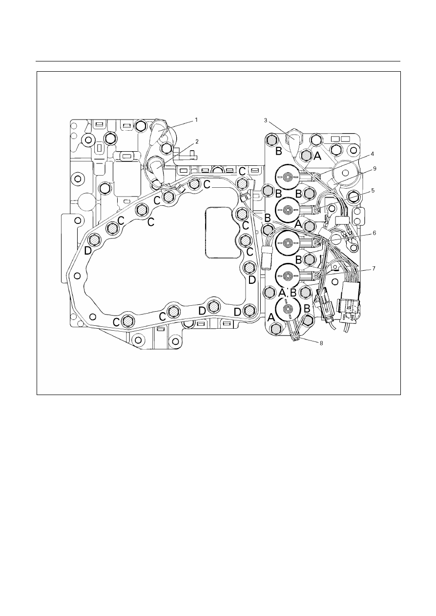
Legend
1. High clutch oil pressure switch
connector (wire color: Gray)
2. 2-4 brake oil pressure switch connector
(wire color: Brown)
3. Low and reverse brake oil pressure
switch connector (wire color: White)
4. Low and reverse brake duty solenoid
connector (wire color: Pink and White)
5. High clutch duty solenoid connector
(wire color: Green and Gray)
6. Lock-up duty solenoid connector (wire
color: Yellow and Black)
7. 2-4 brake duty solenoid connector (wire
color: Blue and Brown)
8. Low clutch duty solenoid connector (wire
color: Orange and Black)
9. Line pressure solenoid connector (wire
color: Pink)