Isuzu D-Max / Isuzu Rodeo (TFR/TFS). Manual - part 1783


  Index      Ford     Isuzu D-Max / Isuzu Rodeo TFR/TFS series - service repair manual 1997-2003 year


Search            


Content   ..  1781  1782  1783  1784   ..


Isuzu D-Max / Isuzu Rodeo (TFR/TFS). Manual - part 1783


ON-VEHICLE SERVICE (JR405E)  7A3-21 

4.  Remove the shift cable from the transmission. 

P1010068

5.  Remove the rear propeller shaft assembly. 

6. Loosen (do not remove) the nuts securing the

exhaust manifold and the exhaust pipe. 

7. 

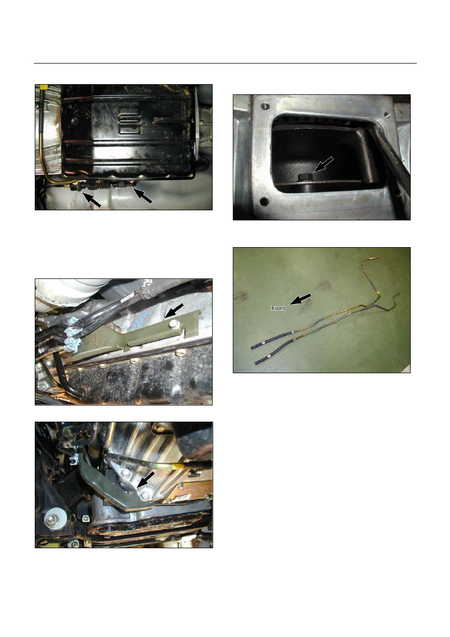
Disconnect the harness connectors from the

transmission. 

8.  Remove the fuel pipe bracket. 

P1010013


P1010014

9.  Remove the ATF level dipstick and tube. 

10. Remove  the  undercover. 


11. 

Rotate the ring gear and remove the 6 torque 

converter bolts. 

P1010016

12. 

Remove the automatic transmission fluid cooling 

pipe. 

P1010060

13. Place a jack beneath the engine to support it. 

14. Remove the 3rd crossmember. 

15. Remove the transmission mount. 

16. Lower the jack beneath the engine slightly to tilt the 

engine and transmission.  Do not allow the radiator 

and air conditioner hoses to stretch. 

17. Remove the bolts attaching the transmission to the 

engine. 

18. 

Lower the transmission from beneath the vehicle. 

Take care not to damage the breathers. 


Install or Connect 

1.  Install the transmission to the engine and tighten the 

bolts. 


Bolt torque : M10  40 N·m (30 lb·ft) 


M12 

76 

N·m (56 lb·ft) 

2.  Install the cable bracket to the transmission. 

3.  Connect the engine harness connectors. 


7A3-22  ON-VEHICLE SERVICE (JR405E) 


4.  Install the 3rd crossmember. 
 

Bolt and Nut torque : 67 N·m (49 lb·ft) 


Bolt torque : 50 N·m (37 lb·ft) 

5.  Install the automatic transmission fluid cooling pipe.

6.  Install the torque converter bolts. 
 

Bolt torque : 29 N·m (22 lb·ft) 

7. Install the undercover. 
 

Bolt torque : 9 N·m (78 lb·in) 

8.  Install the ATF level dipstick and tube. 

9.  Install the fuel hose bracket. 
 

Bolt torque : 6 N·m (52 lb·in) 


10. Tighten the nuts securing the exhaust manifold and 

the exhaust pipe. 


Bolt torque : 43 N·m (32 lb·ft) 

11. Install the rear propeller shaft assembly. 
 

Flange bolt torque : 63 N·m (46 lb·ft) 


Center bearing bracket bolt torque :  

 69 

N·m (51 lb·ft) 

12. Install the shift cable. 

13. Connect the negative battery cable. 

14. Remove the safety stands. 

15. Remove the wheels blocks. 


Torque Specifications 


RTW37ALF001501 


UNIT REPAIR (JR405E)  7A4-1 

SECTION 7A4 

UNIT REPAIR (JR405E) 

TABLE OF CONTENTS 

 PAGE 

Automatic Transmission Disassembly .....................................................................   7A4 -  2 

Control Valve Assembly  ............................................................................................   7A4 -  11 

Control Valve Upper Body  ........................................................................................   7A4 -  18 

Control Valve Lower Body  ........................................................................................   7A4 -  23 

Oil Pump Assembly  ...................................................................................................   7A4 -  28 

Clutch Pack (Reverse and High Clutch Assembly) .................................................   7A4 -  33 

Carrier and Low Clutch Assembly  ...........................................................................   7A4 -  41 

Transmission Case ....................................................................................................   7A4 -  54 

Bearing and Bearing Race Installation Position  .....................................................   7A4 -  66 

Automatic Transmission Reassembly  .....................................................................   7A4 -  69 

Service Standard  .......................................................................................................   7A4 -  83 

Special Service Tool ..................................................................................................   7A4 -  85 


7A4-2  UNIT REPAIR (JR405E) 


AUTOMATIC TRANSMISSION 

DISASSEMBLY 

Cleaning the automatic transmission 

1.  Use compressed steam and /or cleaning oil to thoroughly 

clean the outside of the transmission before disassembly.

CAUTION: 
Steam under high pressure may cause dirt particles 
adhering to the transmission to fly through the air at great 
speed. These particles can cause serious eye injury. Wear 
protective goggles when steam-cleaning the outside of 
the transmission. 
2.  During disassembly, clean the removed parts with cleaning 

oil. Dry the parts with compressed air. 
Use Compressed air to clean the transmission oil holes 
and oil passages. 


Automatic transmission disassembly cautions 

• 

Perform the disassembly procedure in a dust-free 
environment to prevent the entry of foreign material into 
the transmission. 

• 

Inspect each transmission part as you remove it. 

• 

Carefully check the oil pan and the magnet for foreign 
material. This is a good way to estimate transmission 
condition. 

• 

Use your bare hands or vinyl gloves to disassemble the 
transmission. Do not use ordinary work gloves (loose 
threads from the gloves may fall into the transmission and 
cause problems). 

• 

Use a plastic hammer to loosen the transmission case 
and other aluminum parts during disassembly. Strike 
around the parts lightly with the hammer. Do not pry 
aluminum parts away from each other with a screwdriver 
or similar object. 

• 

Arrange the disassembled parts neatly in the order they 
were removed. Cover the parts with a plastic sheet or 
similar object to protect them from dust. 


Content   ..  1781  1782  1783  1784   ..