Isuzu D-Max / Isuzu Rodeo (TFR/TFS). Manual - part 1713


  Index      Ford     Isuzu D-Max / Isuzu Rodeo TFR/TFS series - service repair manual 1997-2003 year


Search            


Content   ..  1711  1712  1713  1714   ..


Isuzu D-Max / Isuzu Rodeo (TFR/TFS). Manual - part 1713


6D3-10  STARTING AND CHARGING SYSTEM

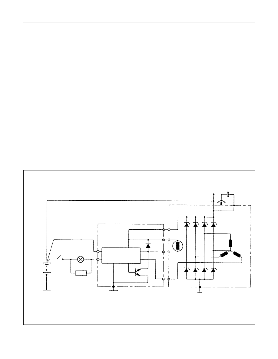
The generator has four external connections; the "B+" lead to
battery positive, "L" lead to the warning lamp circuit(max. 2
watts), "S" lead to battery positive terminal for battery sensing
and an earth connection.

Explanation of type inscripiton

Example:KC-A--> 14V 50-90A.

K

= Code for Stator OD(126mm OD).

C

= Compact Generator.

A

= Ausland (countries other than Germany)

>

= Direction of rotation(clockwise).

14V = Generator Operating Voltage.
50A = Stabilised output at 25 C at 1800 RPM./13.5

Volts.

90A = Stabilised output at 25 C at 1800 RPM./13.5

Volts.

Generator Connetions.

B+ : Battery Main Connection (battery positive)
S

: Battery Sense Connection(battery positive)

L

: Waring lamp(via warning lamp to Ignition switch)

BATT.SENSE

REGULATOR ASSEMBLY

HYBR10

ALTERNATOR ASSEMBLY

12V BATT.

1GN.SW.

300a*

WARN.LAMP

1.2 WATT

L

S

8+

SUPPRESSOR
CAPACITOR
0.5

µf

NOTE: * RESISTOR IS RECOMMENDED TO

ENSURE THAT THE GENERATOR
REMAINS FUNCTIONAL IN CASE OF
WARNING LAMP FAILURE

STARTING AND CHARGING SYSTEM  6D3-11

Warning

Do not reverse S and L connections as this will destroy the
warning lamp circuit of the regulator.
Ensure good electrical contact beween generator  earth and
battery negative,

Operation

With the Iginiton switch turnded "ON", current is supplied via
the warning lamp to the "L" terminal of the regulator. Base
current is fed to T15 causing it to turn on, current then flows
from B+ through the rotor winding via the regulator brushes
and the collector emitter junction of T15 to earth completing the
circuit.  The current in the rotor causes a magnetic field
between adjacent poles to be created, this field is rotated and
cuts the windings of the stator at right angles inducing a
voltage into them.
As the speed is increased this induced voltage increases and
results in curent being rectified in the 3 phase diode bridge and
supplied as DC to the B+ output and hence to the battery.
When the voltage at the B+ terminal of the battery reaches
around 14.2 volts, this voltage is monitored by the "S" lead and
turns the regulator Hybrid base current to T15 OFF removing
rotor current, resulting in a decrease in output voltage to below
the regulating voltage, T15 base current turns ON and the
whole cycle is repeated very rapidly.
D38 protects T15 and the regulator against the back voltage
developed across the rotor winding when T15 turns OFF.
The new generated EP regulators incorporate current limiting in
the warning lamp circuit.

Backup Regulation

The EP regulator will limit the output voltage to a safe level
should either the main B+ cable or the battery sense wire
become decoupled, the output voltage will be slightly above the
normal setting(1-3 volts).

Start up phase

When the Iginition switch is turned on and the engine is not
running, the current to the rotor is reduced by switching it on
and off at a 50% duty cycle, the frequency is approximately 4
KHz and may be audible at times.
This is quite normal, once the engine is started normal
regulation commences.

Warning lamp failure

Should the warning lamp fail, the generator will self excite by
deriving a small current from the phase connecion allowing the
voltage to build up to regulating level.
Note: no filed current will flow when the engine is cranking.

6D3-12  STARTING AND CHARGING SYSTEM

Diagnosis

The EP regulator incorporates diagnostics which will illuminate
the warning lamp as a result of fault conditions in the generator
and external circuitry.

These conditions include:
1. An  open  circuit  in  the  regulator  battery  sensing  wire  (S

Terninal)

2. An open circuit or excessive voltage drop in the B+ cable.

3. An open circuit in the generator phase connection.

4. Overcharging of the battery.

5. Regulator output stage short circuit.

6. Open circuit rotor.

The regulator compares the voltage at B+ with the voltage at
the "S" terminal connceted to battery positive.  If the voltage
differential exceeds a predetermined threshold, the regulator
will operate in backup mode to limit the output voltage to a safe
level.  The warning lamp; will remain illuminated as along as
these conditions prevail.
Sources of high resistance which will trigger the warning lamp
are:

a. Poor contact in wiring harness connectors.

b. Poor contact between rectifier and regulator.

c. High resistance in fusible link assembly.

Caution:
When bench testing the generator it is important that the
warning lamp wattage of 2 watts is not exceeded.
Reversal of the "S" and "L" on the regulator will damage
the regulator.
The correct plug for the regulator is a 9 122 067 011 for the
Bosch tye and for the Shinagawa connector the number is
X02FW.

See appendix 1 for daignostic matrix.
Before testing or disassembling the generator please observe
the following points.

1. When  testing  the  diodes  with  AC  type  testers  the  RMS.

Vlotage  output  must  not  exceed  12.0  volts,  it  is

recommended  that  the  stator  should  be  disconnected

during this test.

2. Where  zener  power  diodes  are  used,  the  breakdown

voltage should be tested to ensure all diodes have the same

zener voltage.

3. Insulation tests on the rotor and stator should use a voltage

not  exceeding  110v  for  a  series  test  lamp.    The  rectifier

must be disconnected from the stator prior to testing.

4. When  carrying  out  repairs  to  the  charging  system  always

disconnected the battery negative first, and reconnect it last.

STARTING AND CHARGING SYSTEM  6D3-13

5. During  current  output  tests  please  make  sure  that  the

ammeter is securely connceted into the charge circuit.

6. Some  battery  powered  timing  lights  can  produce  high

transient  voltages  when  connected  or  disconnected.    Only

disconnect  or  connect  timing  lights  when  the  engine  is

switched off.

7. Make  sure  the  warning  lamp  circuit  is  functioning  normally

before commencing tests.

8. Battery  isolation  switches  must  only  be  operated  when  the

engine is stopped.

9. To  protect  the  charging  system  when  using  240  volt

chargers  it  is  recommeneded  that  the  battery  is

disconnected whilst charging.

10.Due to the very low resistance value of the stator winding it

may  not  be  possible  to  obtain  accurate  readings  without

special equipment.

11.12 volts must never be connected to the "L" terminal of the

regulator as this will damage the lamp driver circuit.

12.No loads apart from the warning lamp can be connected to

the  "L"  termainal.    The  "W"  terminal  is  provided  for  this

purpose.

Disassembly

1. Mark the relative positions of the end housings in relation to

the  stator  assembly  to  aid  reassembly.    Use  a  permanent

marking  pen  do  not  use  centre  punched  as  this  can  cause

misalignmnet of the housings.

2. Remove  the  EP  regulator  from  the  slipring  end  housing  by

removing the two screws. Tilt the regulator slightly from the

plug  connection  until  the  regulator  clears  the  housing,  then

lift clear.

3. Remove the four through bolts.

4. Carefully remove the stator assembly along with the slipring

end housing taking care not to put strain on the stator wires.

5. To  disconnect  the  stator  from  the  rectifier  assembly,  grasp

the  stator  wires  close  to  the  wire  loop  with  a  pair  of  long

nosed  pliers,  heat  the  joint  with  a  soldering  iron,  when  the

point  becomes  plastic  apply  a  slight  twisting  motion  to  the

wires,  then  pull  upwards  to  release  the  wires.  Remove  the

stator.

This  procedure  opens  the  wire  loop  to  release  the  stator

connections easily.

6. To  remove  the  rectifier  remove  the  three  retaining  screw

and the B+ terminal nut and washers.

Note: the B+ bolt and the positive heatsink retaining screw are
fitted with mica insulating washers.
These must be discarded and replaced with new washers and
heatsink compound.


Content   ..  1711  1712  1713  1714   ..