Content .. 1691 1692 1693 1694 ..
Isuzu D-Max / Isuzu Rodeo (TFR/TFS). Manual - part 1693
6A-70 ENGINE MECHANICAL (C24SE, C22NE, 22LE, 20LE)
ENGINE EXTERNAL PARTS
Radiator
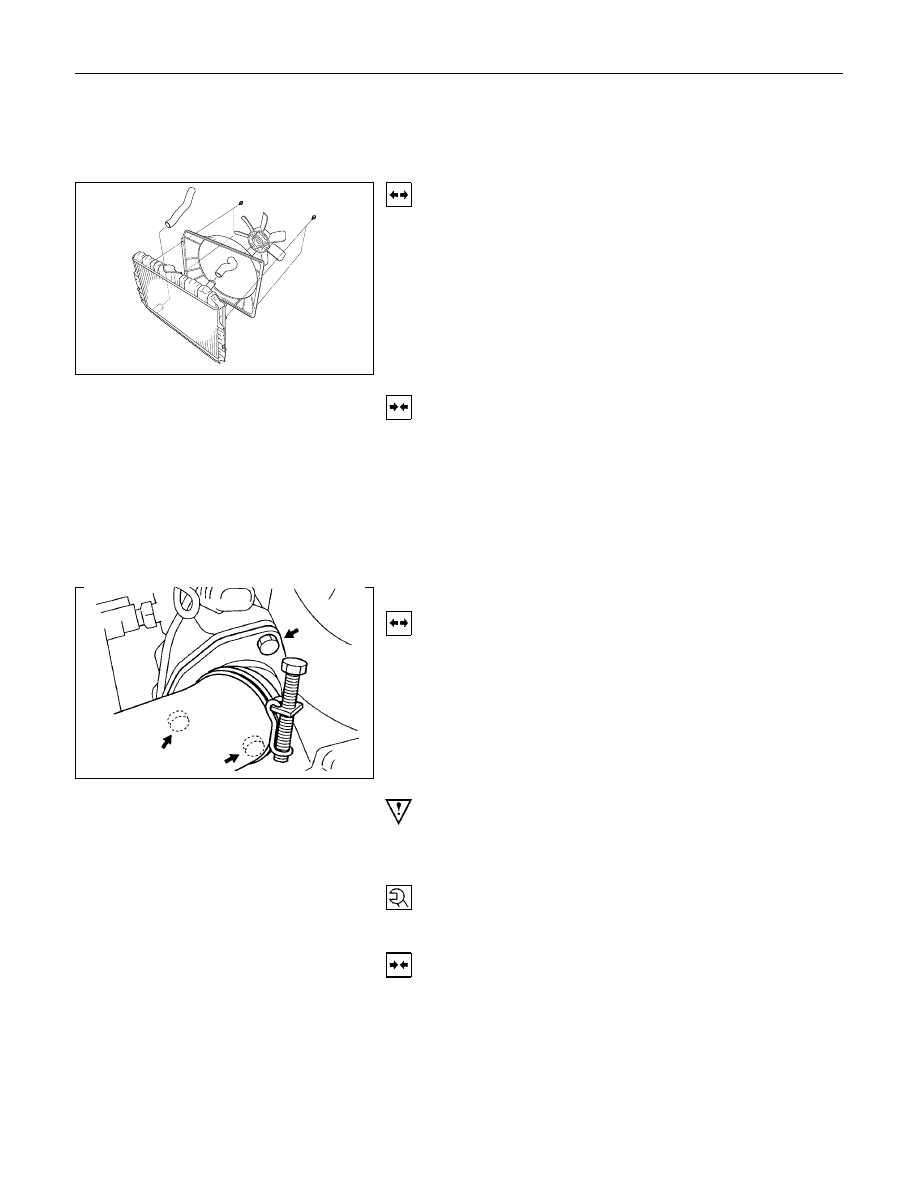
Removal
1.
Remove the upper hose and lower hose.
2.
Remove all V-belts.
3.
Remove the cooling fan.
4.
Remove the fan guide.
5.
Remove the radiator.
Installation
1.
Install the radiator.
2.
Install the fan guide.
3.
Install the cooling fan.
4.
Install all V-belts.
5.
Install the lower and upper hose.
Thermostat
Removal
1.
Remove water outlet nozzles with thermostat from
thermostat housing.
2.
Remove coolant hose and collect coolant.
Important!
Remove and Install thermostat only together with water outlet
nozzles.
Tighten (Torque)
Water outlet nozzles to thermostat housing - 8 N
⋅m (0.8 kgf⋅m)
Installation
1.
Install coolant hose.
2.
Fill cooling system and bleed according to the
corresponding operation.