Isuzu D-Max / Isuzu Rodeo (TFR/TFS). Manual - part 128
6E–116
4JH1 ENGINE DRIVEABILITY AND EMISSIONS
temperature is cold, and it will be low when the engine
temperature is hot.
The output voltage excessively high or low, DTC P0115
(Symptom Code 1) or P0115 (Symptom Code 2) will be
stored.
Diagnostic Aids
An intermittent may be caused by the following:
• Poor connections.
• Misrouted harness.
• Rubbed through wire insulation.
• Broken wire inside the insulation.
Check for the following conditions:
• Poor connection at ECM-Inspect harness connectors
for backed out terminals, improper mating, broken
locks, improperly formed or damaged terminals, and
poor terminal to wire connection.
• Damaged harness-Inspect the wiring harness for
damage. If the harness appears to be OK, observe
the “Coolant Temperature” display on the Tech2 while
moving connectors and wiring harness related to the
sensor.
Diagnostic Trouble Code (DTC) P0115 (Symptom Code 1) (Flash Code 14)
Engine Coolant Temperature Sensor Circuit High Input
Step
Action
Value(s)
Yes
No
1
Was the “On-Board Diagnostic (OBD) System Check”
performed?
—
Go to Step 2
Go to On Board
Diagnostic
(OBD) System
Check
2
1. Connect the Tech 2.
2. Review and record the failure information.
3. Select “F0: Read DTC Infor As Stored By ECU” in
“F0: Diagnostic Trouble Codes”.
Is the DTC P0115 (Symptom Code 1) stored as
“Present Failure”?
—
Go to Step 3
Refer to
Diagnostic Aids
and Go to Step
3
3
1. Using the Tech 2, ignition “On” and engine “Off”.
2. Select “F1: Clear DTC Information” in “F0:
Diagnostic Trouble Codes” with the Tech 2 and
clear the DTC information.
3. Operate the vehicle and monitor the “F0: Read
DTC Infor As Stored By ECU” in the “F0:
Diagnostic Trouble Codes”.
Was the DTC P0115 (Symptom Code 1) stored in this
ignition cycle?
—
Go to Step 4
Refer to
Diagnostic Aids
and Go to Step
4
4
Check for poor/faulty connection at the ECT sensor or
ECM connector. If a poor/faulty connection is found,
repair as necessary.
Was the problem found?
—
Verify repair
Go to Step 5
5
Visually check the ECT sensor.
Was the problem found?
—
Go to Step 12
Go to Step 6
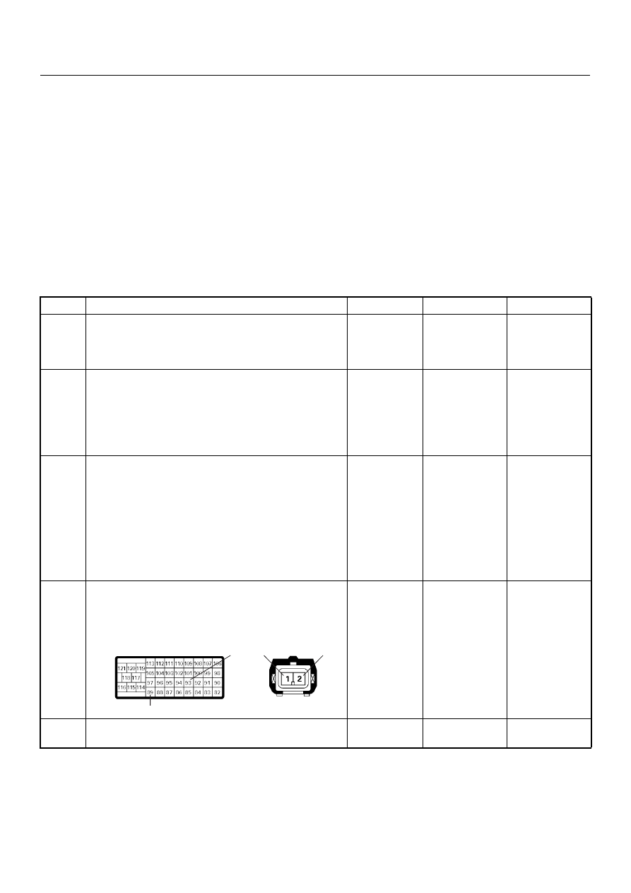
93
2
1
89
E-41
C-57(B)