Isuzu D-Max / Isuzu Rodeo (TFR/TFS). Manual - part 1204


  Index      Ford     Isuzu D-Max / Isuzu Rodeo TFR/TFS series - service repair manual 1997-2003 year


Search            


Content   ..  1202  1203  1204  1205   ..


Isuzu D-Max / Isuzu Rodeo (TFR/TFS). Manual - part 1204


8-156  ELECTRICAL-BODY AND CHASSIS 

HORN 

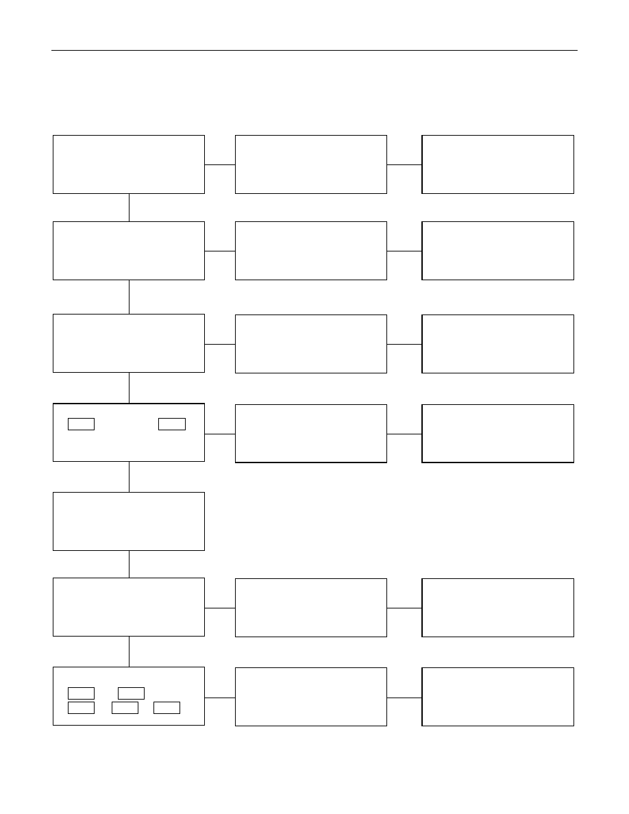
1.  Both sides of horn do not sound 
 

Checkpoint  

Trouble 

Cause 


Countermeasure 


Repair the grounding point

Poor ground contact

NG

Horn relay

Grounding point

Reinstall or replace fuse No.
EB-2 (10A)

Fuse No EB-2 (10A, Relay
and fuse box)

Poor fuse contact or blown
fuse

NG

OK

OK

Reinstall or replace the horn
relay

Poor relay contact or faulty
horn relay

NG

Voltage between connector

X-4

 - ground or 5 

X-4

- ground (Should be battery
voltage present)

OK

Repair open circuit or
reconnect the connector

Open circuit or poor connector
contact between fuse No. EB-
2 (10A) and horn relay

NG

Remove steering pad and
steering wheel

OK

Horn switch continuity

OK

Repair or replace the horn
switch

Poor switch point contact or
faulty switch

NG

Continuity between

X-4

 - 12 

C-42

X-4

 - 1 

C-20

 (1 

C-21

)

OK

Repair open circuit or
connector contact

Open circuit or poor connector
contact

NG


ELECTRICAL-BODY AND CHASSIS  8-157 

2.  One side of horn does not blow 
 

Checkpoint  

Trouble 

Cause 


Countermeasure 


Repair open circuit or
reconnect the connector

Open circuit or poor connector
contact

NG

Voltage between 1 

C-20

(1 

C-21

) - ground with

horn switch depressed
(Should be battery voltage
present)

Replace the horn assembly

Horn continuity between
connectors

Faulty horn assembly

NG

OK


3.  Insufficient horn volume 
 

Clfean and/or remove the
foreign material

Stain foreign material in the
horn

NG

Horn

Recharge or replace the
battery

Battery condition

Discharged battery

NG

OK


8-158  ELECTRICAL-BODY AND CHASSIS 


  REMOVAL AND INSTALLATION 


REAR COMBINATION LIGHT 
Stoplight 

Removal 

1.  Open the rear gate. 
2.  Remove the screws of rear combination light. 
3.  Remove the rear combination light assembly. 


4.  Turn the bulb 

2

 counterclockwise to remove it. 


Installation 

Follow the removal procedure in the reverse order to install the 
rear combination light. 
Pay close attention to the important points mentioned in the 
following paragraphs. 


Bulb 

Be absolutely sure that each bulb is correctly installed. 
This will prevent a poor contact and an open circuit. 
 

ELECTRICAL-BODY AND CHASSIS  8-159 


FRONT TURN LIGHT 

Removal 

1.  Remove the screws of the front turn light. 
2.  Pull out the light housing for front turn light from bumper. 


3.  Push the bulb in and turn it counterclockwise to remove it

from the light housing. 


Installation 

Follow the removal procedure in the reverse order to install the 
front turn light. 
Pay close attention to the important points mentioned in the 
following paragraphs. 


Bulb 

Be absolutely sure that the front turn light bulb is correctly 
installed. 
This will prevent a poor contact and an open circuit. 


Content   ..  1202  1203  1204  1205   ..