Content .. 1194 1195 1196 1197 ..
Isuzu D-Max / Isuzu Rodeo (TFR/TFS). Manual - part 1196
8-124 ELECTRICAL-BODY AND CHASSIS
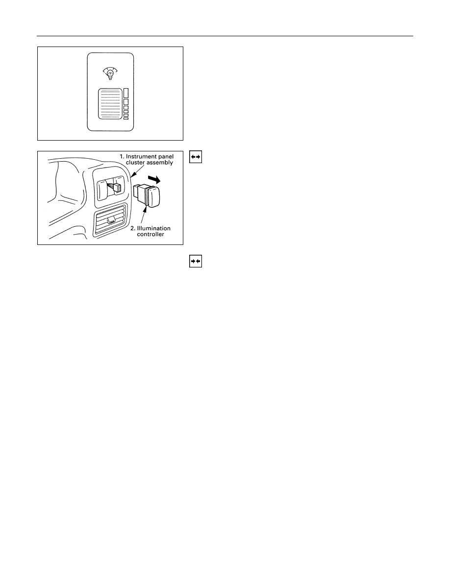
ILLUMINATION CONTROLLER
Turning the illumination controller knob upward increases the
brightness of each illumination light, turning it downward
decreases its brightness.
Removal
1. Instrument Panel Cluster Assembly
· Refer to Section 10 “BODY” for instrument panel cluster
assembly removal steps.
2. Illumination Controller
· Disconnect the switch connector.
· To remove the switch, push the lock from the back side
of the cluster assembly.
Installation
To install, follow the removal procedure in the reverse order.
Connector
Be absolutely sure that the illumination controller connector is
securely connected.
This will prevent a poor contact and an open circuit.